COMPRESSION INSPECTION
BHE011002000W03
-
Warning
-
• Hot engines can cause severe burns. Be careful not to burn yourself during removal/installation of each component.
-
• Fuel vapor is hazardous. It can very easily ignite, causing serious injury and damage. Always keep sparks and flames away from fuel.
1. Remove the engine cover.
2. Verify that the battery is fully charged. (See BATTERY INSPECTION.)
3. Warm up the engine.
4. To decrease the exhaust system temperature, stop the engine and leave it as it is for approx. 10 min.
5. Remove the trailing or leading side spark plug of the front and rear rotors. (See SPARK PLUG REMOVAL/INSTALLATION.)
6. Disconnect the eccentric shaft position sensor connector. (See ECCENTRIC SHAFT POSITION SENSOR REMOVAL/INSTALLATION.)
-
Caution
-
• To cut the fuel injection and ignition, make sure the eccentric shaft position sensor connector is disconnected.
7. Measure the compression pressure using the following procedure.
-
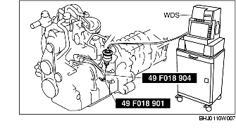
(1) Install the SST (49 F018 901) to the trailing or leading side plug hole of the rotor housing.

-
(2) Set the SST (49 F018 9A0B) as shown in the figure.
-
• When using the WDS or equivalent, set the WDS or equivalent to the SST (49 F018 901, 49 F018 904) as shown in the figure.
-
(3) Depress the accelerator pedal fully and crank for 5-10 s.
-
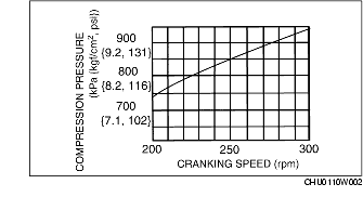
(4) Read the compression and engine speed.
-
Compression pressure
-
• Standard: 830 kPa {8.5 kgf/cm2, 120 psi} [250 rpm]
-
• Minimum: 680 kPa {6.9 kgf/cm2, 98.6 psi} [250 rpm]
-
• Difference in chambers: Within 150 kPa {1.5 kgf/cm2, 21.8 psi}
-
• Difference in rotors: Within 100 kPa {1.0 kgf/cm2, 14.5 psi}
-
(5) Perform the same procedure for the other rotor housing.
-
(6) If the compression is at the minimum or less, or the difference in the chambers and difference in the rotors is at the minimum or more, overhaul.
-
Caution
-
• If the engine speed when measuring compression differs from the standard, adjust according to the graph.
8. Install the spark plugs. (See SPARK PLUG REMOVAL/INSTALLATION.)
9. Connect the eccentric shaft position sensor connector. (See ECCENTRIC SHAFT POSITION SENSOR REMOVAL/INSTALLATION.)
10. Install the engine cover.