BAROMETRIC PRESSURE (BARO) SENSOR INSPECTION
BHE014018210W02
-
Note
-
• Before performing the following inspection, make sure to follow the troubleshooting flowchart. (See Troubleshooting Procedure.)
Voltage Inspection
1. Remove the BARO sensor with the connector still connected.
2. Remove the BARO sensor hose.
3. Turn the ignition switch to the ON position.
4. Verify that the voltage at PCM terminal 5S (WDS PID: BARO) is within the specification.
-
• If not within the specification even though the related wiring harnesses have no malfunction, replace the BARO sensor (See BAROMETRIC PRESSURE (BARO) SENSOR REMOVAL/INSTALLATION.).
-
BARO sensor output voltage
-
2.4-4.7 V
5. Install the vacuum pump.
6. Verify that the change in voltage at PCM terminal 5S (WDS PID: BARO) is within the specification when a vacuum of 30 kPa {0.30 kgf/cm2, 4.4 psi} is applied.
-
• If not within the specification, replace the BARO sensor. (See BAROMETRIC PRESSURE (BARO) SENSOR REMOVAL/INSTALLATION.)
-
BARO sensor output voltage variance
-
1.06-1.30 V
-
Note
-
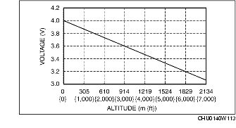
• The voltage shown in the figure may vary excessively depending on the weather or battery conditions.
BARO sensor characteristics graph (reference)
Circuit Open/Short Inspection
1. Disconnect the PCM connectors.
2. Disconnect the BARO sensor connector.
3. Inspect the following wiring harnesses for open or short circuit. (Continuity inspection)
Open circuit
-
• If there is no continuity in the following wiring harnesses, there is an open circuit. Repair or replace the wiring harness.
-
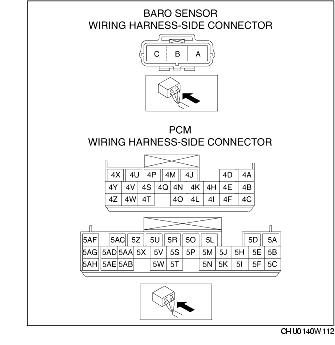
– BARO sensor terminal A and PCM terminal 5S
-
– BARO sensor terminal B and PCM terminal 4U
-
– BARO sensor terminal C and PCM terminal 4K
Short circuit
-
• If there is continuity in the following wiring harnesses, there is a short circuit. Repair or replace the wiring harness.
-
– BARO sensor terminal A and body ground
-
– BARO sensor terminal A and power supply
-
– BARO sensor terminal C and body ground
-
– BARO sensor terminal C and power supply