KNOCK SENSOR (KS) INSPECTION
BHE014018920W02
Resistance Inspection
-
Note
-
• Before performing the following inspection, make sure to follow the troubleshooting flowchart. (See Troubleshooting Procedure.)
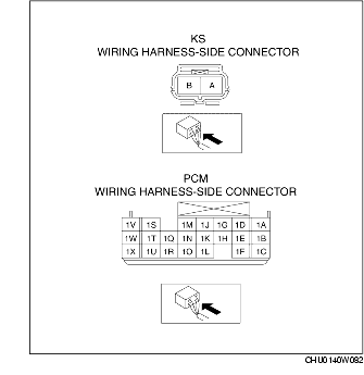
1. Disconnect the KS connector.
2. Measure the resistance between KS terminals A and B.
-
• If not within the specification, replace the KS. (See KNOCK SENSOR (KS) REMOVAL/INSTALLATION.)
-
• If the monitor item condition/specification (reference) is not within the specification, even though the KS resistance is within the specification, perform the "Circuit Open/Short Inspection".
-
KS resistance
-
120-280 kilohms
Circuit Open/Short Inspection
1. Disconnect the PCM connector.
2. Disconnect the KS connector.
3. Inspect the following wiring harnesses for open or short. (Continuity inspection)
Open circuit
-
• If there is no continuity in the following wiring harnesses, there is an open circuit. Repair or replace the wiring harness.
-
– KS terminal A and PCM terminal 1T
-
– KS terminal B and PCM terminal 1F
Short circuit
-
• If there is continuity in the following wiring harnesses, there is a short circuit. Repair or replace the wiring harness.
-
– KS terminal A and body ground
-
– KS terminal A and power supply
-
– KS terminal B and body ground
-
– KS terminal B and power supply