|
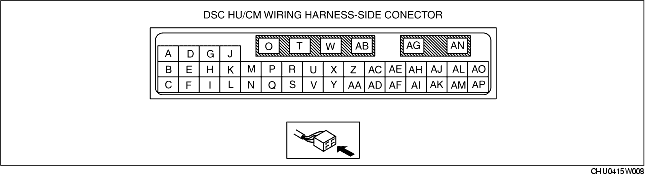
Terminal
|
Signal name
|
Connected to
|
Measured item
|
Measured terminal (measured condition)
|
Standard
|
Inspection item(s)
|
|
A
|
Yaw rate (reference signal)
|
Combined sensor
|
Continuity
|
A-combined sensor connector terminal A
|
Continuity detected
|
• Wiring harness (A-combined sensor connector terminal A)
|
|
B
|
Brake fluid pressure (signal)
|
Brake fluid pressure sensor
|
Continuity
|
B-brake fluid pressure sensor connector terminal B
|
Continuity detected
|
• Wiring harness (B-brake fluid pressure sensor connector terminal B)
|
|
C
|
Power supply (brake fluid pressure sensor)
|
Brake fluid pressure sensor
|
Continuity
|
C-brake fluid pressure sensor connector terminal C
|
Continuity detected
|
• Wiring harness (C-brake fluid pressure sensor connector terminal C)
|
|
D
|
Yaw rate (test signal)
|
Combined sensor
|
Continuity
|
D-combined sensor connector terminal C
|
Continuity detected
|
• Wiring harness (D-combined sensor connector terminal C)
|
|
E
|
Ground
(brake fluid pressure sensor)
|
Brake fluid pressure sensor
|
Continuity
|
E-brake fluid pressure sensor connector terminal A
|
Continuity detected
|
• Wiring harness (E-brake fluid pressure sensor connector terminal A)
|
|
F
|
Yaw rate (signal)
|
Combined sensor
|
Continuity
|
F-combined sensor connector terminal B
|
Continuity detected
|
• Wiring harness (F-combined sensor connector terminal B)
|
|
G
|
Lateral-G (signal)
|
Combined sensor
|
Continuity
|
G-combined sensor connector terminal D
|
Continuity detected
|
• Wiring harness (G-combined sensor connector terminal D)
|
|
H
|
CAN_H
|
DLC-2 (CAN_H)
|
Continuity
|
H-DLC-2 terminal CAN_H
|
Continuity detected
|
• Wiring harness (H-DLC-2 terminal CAN_H)
|
|
I
|
CAN_L
|
DLC-2 (CAN_L)
|
Continuity
|
I-DLC-2 terminal CAN_L
|
Continuity detected
|
• Wiring harness (I-DLC-2 terminal CAN_L)
|
|
J
|
-
|
-
|
-
|
-
|
-
|
-
|
|
K
|
Power supply
(system)
|
Ignition switch
|
Voltage
|
Ignition switch at ON
|
B+
|
• Wiring harness (K-ignition switch)
|
|
Ignition switch is off.
|
1 V or less
|
-
|
|
L
|
Power supply (combined sensor)
|
Combined sensor
|
Continuity
|
L-combined sensor connector terminal E
|
Continuity detected
|
• Wiring harness (L-combined sensor connector terminal E)
|
|
M
|
-
|
-
|
-
|
-
|
-
|
-
|
|
N
|
-
|
-
|
-
|
-
|
-
|
-
|
|
O
|
Power supply
(solenoid operation)
|
Battery
|
Voltage
|
Under any condition
|
B+
|
• Wiring harness (O-battery)
|
|
P
|
Ground (combined sensor)
|
Combined sensor
|
Continuity
|
P-combined sensor connector terminal F
|
Continuity detected
|
• Wiring harness (P-combined sensor connector terminal F)
|
|
Q
|
-
|
-
|
-
|
-
|
-
|
-
|
|
R
|
-
|
-
|
-
|
-
|
-
|
-
|
|
S
|
-
|
-
|
-
|
-
|
-
|
-
|
|
T
|
Ground
(DSC system)
|
Ground point
|
Continuity
|
T-ground point
|
Continuity detected
|
• Wiring harness (T-ground point)
|
|
U
|
-
|
-
|
-
|
-
|
-
|
-
|
|
V
|
-
|
-
|
-
|
-
|
-
|
-
|
|
W
|
-
|
-
|
-
|
-
|
-
|
-
|
|
X
|
-
|
-
|
-
|
-
|
-
|
-
|
|
Y
|
-
|
-
|
-
|
-
|
-
|
-
|
|
Z
|
-
|
-
|
-
|
-
|
-
|
-
|
|
AA
|
Vehicle speed output
|
Audio unit
|
Continuity
|
AA-audio unit
|
Continuity detected
|
• Wiring harness (AA-audio unit)
|
|
Car-navigation unit
|
AA-car-navigation unit
|
• Wiring harness (AA-car-navigation unit)
|
|
Auto leveling control module
|
AA-auto leveling control module
|
• Wiring harness (AA-auto leveling control module)
|
|
AB
|
-
|
-
|
-
|
-
|
-
|
-
|
|
AC
|
RF wheel-speed sensor (signal)
|
RF ABS wheel-speed sensor
|
Continuity
|
AC-RF ABS wheel-speed sensor connector terminal A
|
Continuity detected
|
• Wiring harness (AC-RF ABS wheel-speed sensor connector terminal A)
|
|
AD
|
Brake switch
|
Brake switch
|
Voltage
|
AD-ground point
(Brake pedal depressed with ignition switch at ON)
|
B+
|
• Wiring harness (AD-brake switch)
• Brake switch
|
|
AD-ground point
(Brake pedal not depressed with ignition switch at ON)
|
1 V or less
|
-
|
|
AE
|
RF wheel-speed sensor (ground)
|
RF ABS wheel-speed sensor
|
Continuity
|
AE-RF ABS wheel-speed sensor connector terminal B
|
Continuity detected
|
• Wiring harness (AE-RF ABS wheel-speed sensor connector terminal B)
|
|
AF
|
RR wheel-speed (signal)
|
RR ABS wheel-speed sensor
|
Continuity
|
AF-RR ABS wheel-speed sensor connector terminal A
|
Continuity detected
|
• Wiring harness (AF-RR ABS wheel-speed sensor connector terminal A)
|
|
AG
|
Power supply
(ABS motor operation)
|
Battery
|
Voltage
|
Under any condition
|
B+
|
• Wiring harness (AG-battery)
|
|
AH
|
LR wheel-speed sensor (signal)
|
LR ABS wheel-speed sensor
|
Continuity
|
AH-LR ABS wheel-speed sensor connector terminal A
|
Continuity detected
|
• Wiring harness (AH-LR ABS wheel-speed sensor connector terminal A)
|
|
AI
|
RR wheel-speed sensor (ground)
|
RR ABS wheel-speed sensor
|
Continuity
|
AI-RR ABS wheel-speed sensor connector terminal B
|
Continuity detected
|
• Wiring harness (AI-RR ABS wheel-speed sensor connector terminal B)
|
|
AJ
|
LF wheel-speed sensor (ground)
|
LF ABS wheel-speed sensor
|
Continuity
|
AJ-LF ABS wheel-speed sensor connector terminal B
|
Continuity detected
|
• Wiring harness (AJ-LF ABS wheel-speed sensor connector terminal B)
|
|
AK
|
LR wheel-speed sensor (ground)
|
LR ABS wheel-speed sensor
|
Continuity
|
AK-LR ABS wheel-speed sensor connector terminal B
|
Continuity detected
|
• Wiring harness (AK-LR ABS wheel-speed sensor connector terminal B)
|
|
AL
|
LF wheel-speed sensor (single)
|
LF ABS wheel-speed sensor
|
Continuity
|
AL-LF ABS wheel-speed sensor connector terminal A
|
Continuity detected
|
• Wiring harness (AL-LF ABS wheel-speed sensor connector terminal A)
|
|
AM
|
-
|
-
|
-
|
-
|
-
|
-
|
|
AN
|
Ground
(ABS motor)
|
Ground point
|
Continuity
|
AN-ground point
|
Continuity detected
|
• Wiring harness (AN-ground point)
|
|
AO
|
KLN
|
DLC-2 (KLN)
|
Continuity
|
AO-DLC-2 terminal KLN
|
Continuity detected
|
• Wiring harness (AO-DLC-2 terminal KLN)
|
|
AP
|
DSC OFF switch
|
DSC OFF switch
|
Continuity
|
AP-DSC OFF switch connector terminal C
|
Continuity detected
|
• Wiring harness (AP-DSC OFF switch connector terminal C)
|