BRAKE FLUID PRESSURE SENSOR INSPECTION
BHE041543771W01
1. Turn the ignition switch to the ON position, then measure the voltage between brake fluid pressure sensor terminal C and ground.
-
• If there is any malfunction, inspect the wiring harness between brake fluid pressure sensor terminal C and DSC HU/CM terminal C, then repair or replace if necessary.
-
Standard voltage
-
4.75-5.25 V
2. Measure the voltage between brake fluid pressure sensor terminal A and the ground.
-
• If there is any malfunction, inspect the wiring harness between brake fluid pressure sensor terminal A and DSC HU/CM terminal E, then repair or replace if necessary.
-
Standard voltage
-
0 V
3. Turn the ignition switch off.
4. Install the SSTs to the master cylinder.
-
Note
-
• Install the SST (49 D043 002) to the master cylinder using a commercially available flare nut wrench.
-
– Flare nut across flat: 12 mm {0.47 in}
5. Bleed the air from the SSTs and the brake line. (Bleed air from the SSTs through air bleeding valve A.)
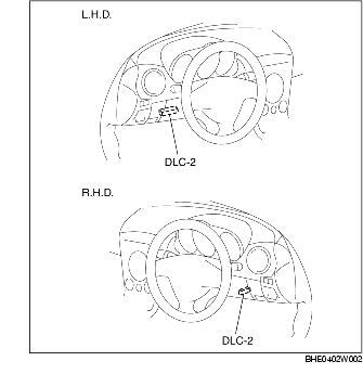
6. Connect the WDS or equivalent to the DLC-2.
7. Select the MCYLIP PID.
8. Start the engine.
9. Depress the brake pedal, and confirm that the fluid pressure value of the SST (Gauge) and the value shown on the WDS or equivalent are equal.
-
• If the fluid pressures are different, replace the DSC HU/CM.