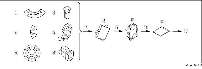
AIR INTAKE CONTROL SYSTEM DIAGRAM
BHE074061190T14
|
1
|
REC/FRESH switch
|
|
2
|
Defroster switch
|
|
3
|
Set temperature
|
|
4
|
Solar radiation amount
|
|
5
|
Ambient temperature
|
|
6
|
Cabin temperature
|
|
7
|
Signal
|
|
8
|
A/C amplifier
|
|
9
|
Output
|
|
10
|
Air intake actuator
|
|
11
|
Operation
|
|
12
|
Air intake door
|
|
13
|
Air intake mode change
|