PROCEDURES FOR DETERMINING THE LOCATION OF A MALFUNCTION
BHE090255430W04
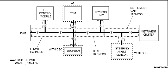
System Wiring Diagram
|
1
|
Wiring harness 1
|
Front harness
|
|
2
|
Wiring harness 2
|
|
3
|
Wiring harness 3
|
|
4
|
Wiring harness 4
|
|
5
|
Wiring harness 5
|
|
6
|
Wiring harness 6
|
Rear harness
|
|
7
|
Wiring harness 7
|
|
8
|
Wiring harness 8
|
Instrument panel harness
|
|
9
|
Wiring harness 9
|
|
10
|
Wiring harness 10
|
PCM
1. Check the display of DTC U0121 and/or U0155, using the SST (WDS or equivalent). (See DTC TABLE [MULTIPLEX COMMUNICATION SYSTEM].)
2. Referring to the following table, determine the malfunctioning part of the CAN system.
|
Module
|
Communication status
|
Malfunction location
|
|
DSC HU/CM
|
TCM
|
Instrument cluster
|
|
PCM
|
Error
|
Error
|
Error
|
• Wiring harness 1
• Wiring harness 3
• PCM
|
|
Error
|
OK
|
OK
|
• Wiring harness 5
• DSC HU/CM
|
|
OK
|
Error
|
OK
|
• Wiring harness 3
• TCM
|
|
OK
|
OK
|
Error
|
• Wiring harness 6
• Wiring harness 8
• Wiring harness 10
• Instrument cluster
|
EPS Control Module
1. Check the display of DTC U1900, using the SST (WDS or equivalent). (See DTC TABLE [MULTIPLEX COMMUNICATION SYSTEM].)
Malfunction location
-
• Wiring harness 1
-
• Wiring harness 2
-
• Wiring harness 3
-
• Wiring harness 5
-
• PCM
-
• DSC HU/CM
-
• EPS control module
DSC HU/CM
1. Check the display of DTC U1900, using the SST (WDS or equivalent). (See DTC TABLE [MULTIPLEX COMMUNICATION SYSTEM].)
Malfunction location
-
• Wiring harness 1
-
• Wiring harness 3
-
• Wiring harness 5
-
• Wiring harness 6
-
• Wiring harness 8
-
• Wiring harness 11
-
• PCM
-
• Steering angle sensor
-
• DSC HU/CM
TCM
1. Check the display of DTC U0100, using the SST (WDS or equivalent). (See DTC TABLE [MULTIPLEX COMMUNICATION SYSTEM].)
Malfunction location
-
• Wiring harness 1
-
• Wiring harness 3
-
• Wiring harness 4
-
• PCM
-
• TCM
Keyless Unit
1. Check the display of DTC U1900, using the SST (WDS or equivalent). (See DTC TABLE [MULTIPLEX COMMUNICATION SYSTEM].)
Malfunction location
-
• Wiring harness 1
-
• Wiring harness 3
-
• Wiring harness 6
-
• Wiring harness 7
-
• PCM
-
• Keyless unit
Steering Angle Sensor
1. Check the display of DTC U1900, using the SST (WDS or equivalent). (See DTC TABLE [MULTIPLEX COMMUNICATION SYSTEM].)
Malfunction location
-
• Wiring harness 9
-
• DSC HU/CM
-
• Steering angle sensor
Instrument Cluster
1. Access and monitor the "PCM_MSG", "EPS_MSG", "TCM_MSG" and "ABS_MSG" of PID using the SST (WDS or equivalent).
2. Referring to the PID/DATA MONITOR, confirm the display status of the PID. (See PID/DATA MONITOR TABLE [MULTIPLEX COMMUNICATION SYSTEM].)
3. Referring to the following table, determine the malfunctioning part of the CAN system.
|
Module
|
Communication status
|
Malfunction location
|
|
TCM
|
DSC HU/CM
|
EPS control module
|
PCM
|
|
Instrument cluster
|
Error
|
Error
|
Error
|
Error
|
• Wiring harness 8
• Wiring harness 10
• Instrument cluster
|
|
Error
|
OK
|
OK
|
OK
|
• Wiring harness 4
• TCM
|
|
OK
|
Error
|
OK
|
OK
|
• Wiring harness 5
• Wiring harness 6
• DSC HU/CM
|
|
OK
|
OK
|
Error
|
OK
|
• Wiring harness 2
• Wiring harness 3
• EPS control module
|
|
OK
|
OK
|
OK
|
Error
|
• Wiring harness 1
• PCM
|