DRIVER SIDE POWER WINDOW SYSTEM OUTLINE


BHE091258000T04

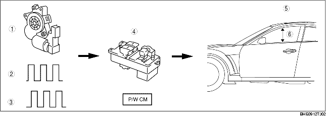
• On the basis of the pulse signals from the Hall effect switches in the power window motor, the power window control module in the power window main switch determines the window position and the operation direction. Accordingly, the power window main switch controls the driver-side power window system.

• When the initial position is set before vehicle delivery, the window position and the operation direction are stored in the power window control module in the power window main switch. Thus resetting the initial position is necessary if the battery negative cable, power window main switch connector, or power window motor connector is disconnected.

Note
• If the initial position has not been set, the driver-side power window system's auto function, the auto window return function and the precise motion function will not function.
• See the workshop manual for more information about setting the initial position. (Mazda RX-8 Workshop Manual 1796-1*-03D)

1
Power window motor
2
Pulse A
3
Pulse B
4
Power window main switch
5
Driver's side door
6
Open/close

Fail-safe function

Detection Condition

Fail-safe

Recovery Items

IG switch ON

IG switch OFF

Hall effect switch No. 1 (for jam-safe and window position detection) operation malfunction
• During up/down movement, Hall effect switch No. 2 pulse detected but Hall effect switch No. 1 pulse not detected
Automatic operation prohibited
Automatic and manual operation prohibited
During up movement, pulse signals for Hall effect switches No. 1 and No. 2 detected normally, and fully closed position and return/non-return ranges redetected
Hall effect switch No. 2 (for window movement direction detection) operation malfunction
• During up/down movement, Hall effect switch No. 1 pulse detected but Hall effect switch No. 2 pulse not detected
Pulse signal malfunction detection (Inversion of input signals of, or large phase deviation between, Hall effect switches No. 1 and No. 2.)
• During up/down movement, difference detected between the direction detection signals from Hall effect switches No. 1 and No. 2, and the actual direction
Non-return range downturn malfunction
• During up movement, the signal input from Hall effect switch No. 1 is higher than the position stored in the P/W main switch
Hall effect switches No. 1 and No. 2 operation malfunction
• Hall effect switches No. 1 and No. 2 pulse signal not detected after down movement initiated from the fully closed position