Let me preface this by stating that I am horrible at documenting projects. I
figured I should probably write up something about my latest project, as I am finding
a lot of conflicting information online.
You may remember my last thread, in which I rebuilt a 12A rotary. Everything is
still fine and well with that car, it has just become an occasional driver.
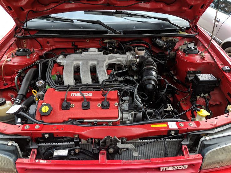
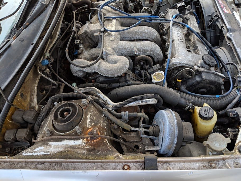
It's a 1985 Mazda Rx-7, 12A engine with dual weber 36DCD carbs. Has pretty much
everything else done to it from suspension to engine.
Sadly, this thread isn't about any rotaries. Changing a waterpump on a rotary isn't
exactly difficult anyway. I did help a friend make a 13b turbo AE86 rotorolla, but
that is for another time.
A few years back, I picked up a new daily driver, a 2010 BMW 335i M-sport. It's
got a 3.0L twin turbo inline six, coupled to a six speed manual transmission. BMW
tossed their sport stuff all over it, so it certainly sets itself apart from a regular
three series. It's also a hoot to drive, the thing is tuned for somewhere around
350-400 horsies and 425 torques.
I've spent most of my time fooling around with coding and software on this car.
It's really neat that you can program each ecu to have different config and enable
new features. I've added things like brake light strobing for stops over a certain
G level, to mundane things like rolling the windows up remotely.
The BMW has an electric water pump. I am sure it will be a pain to change one day,
but today is not that day.
and the standard BMW service shot:
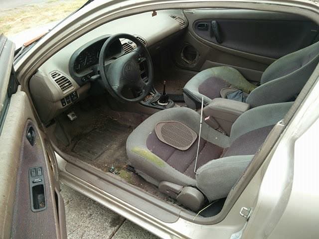
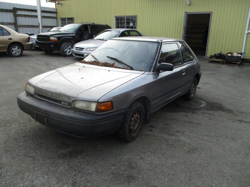
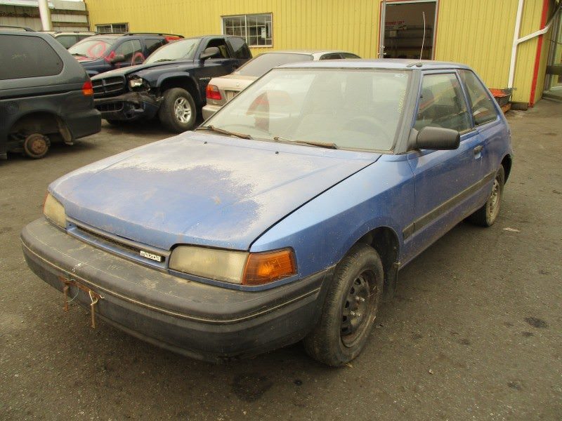
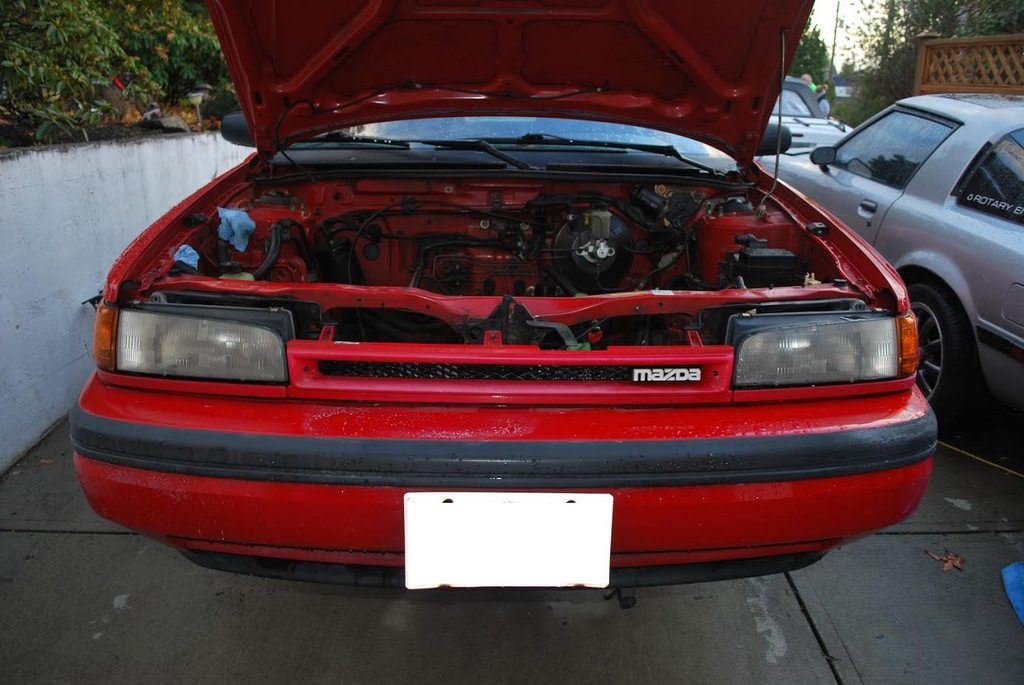
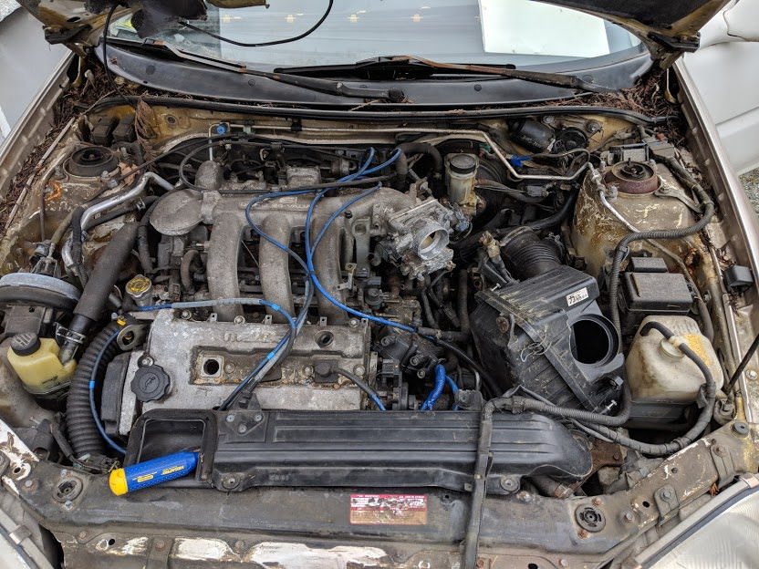
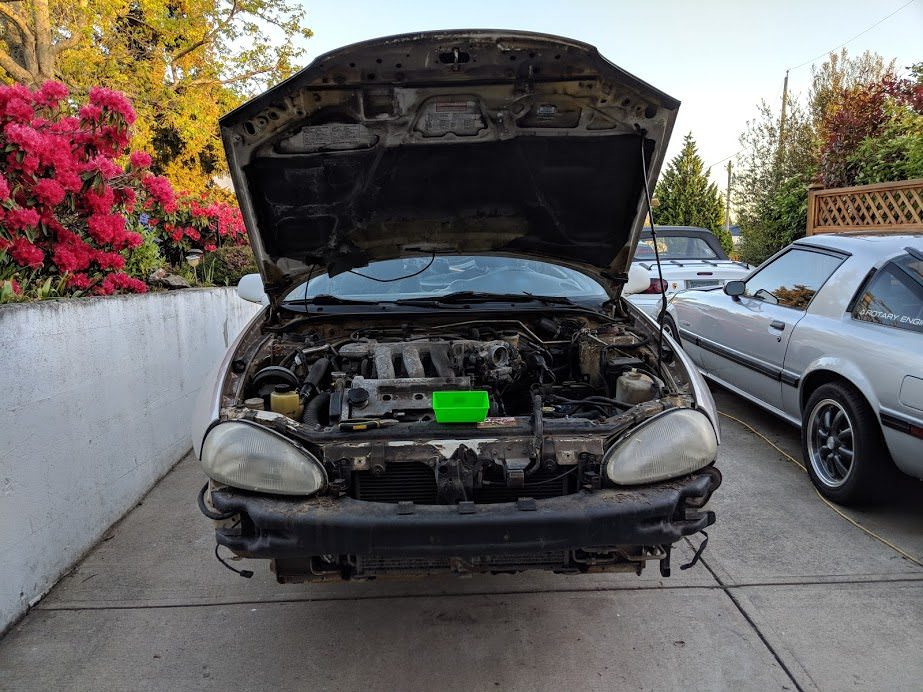
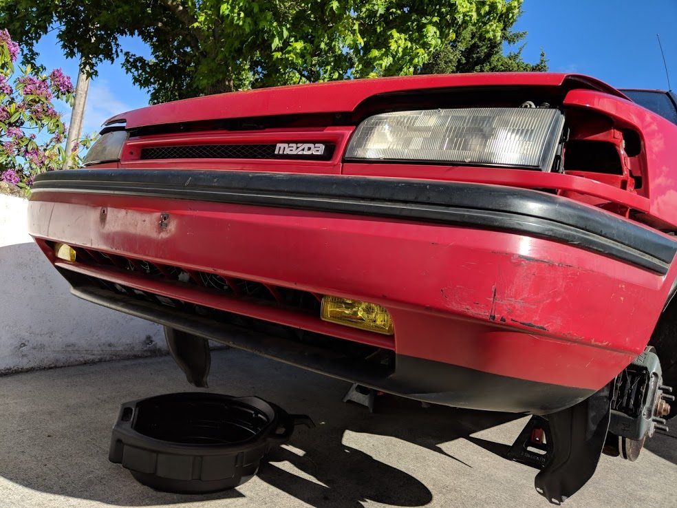
Now where does that leave us. Oh yes. A 1990 Mazda 323 hatchback. This has a peppy
80hp 1.6L 4 cylinder SOHC, coupled to an automatic transmission made of glass. Absolute
hoot to drive, just like a gokart.
(I don't even have a picture, I'll take one tomorrow)
Years back, this used to be my grandmother's car. It's served the family well and
I just can't get rid of it. Unfortunately, this summer, I had some problems with
the cooling system. My mother borrowed it, ran it without coolant and it overheated.
I don't think it warped the head, I did a chemical test for exhaust gasses in the
coolant, a leakdown/compression test etc and they all were okay. I tossed in some
new coolant and ran it for a few more weeks.
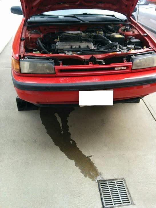
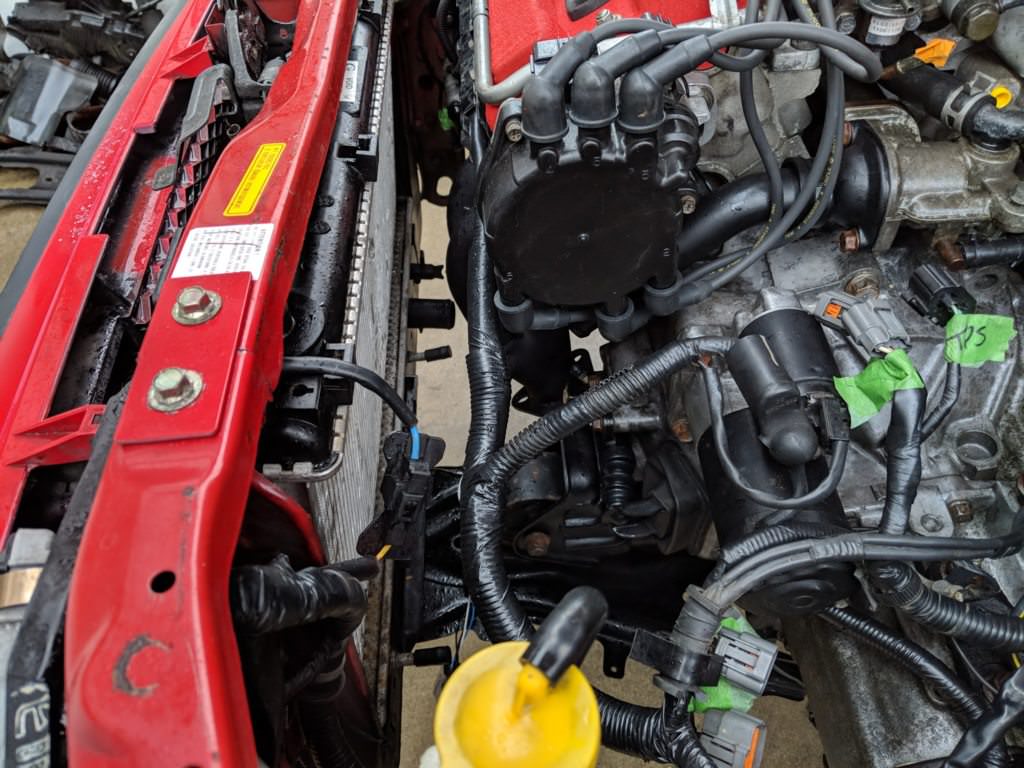
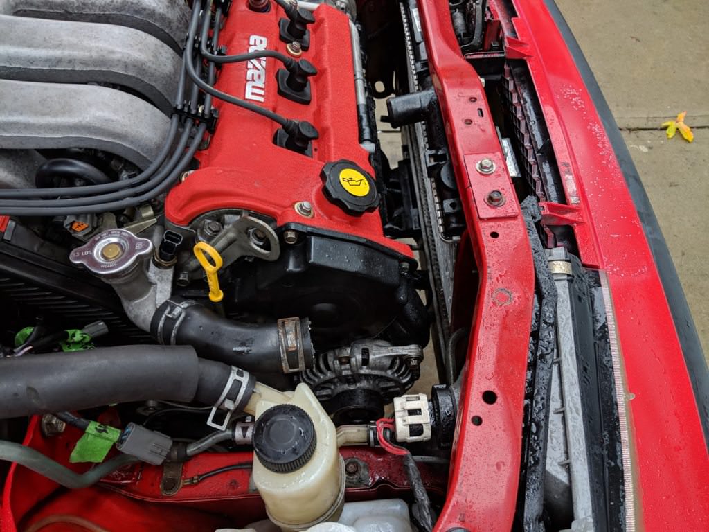
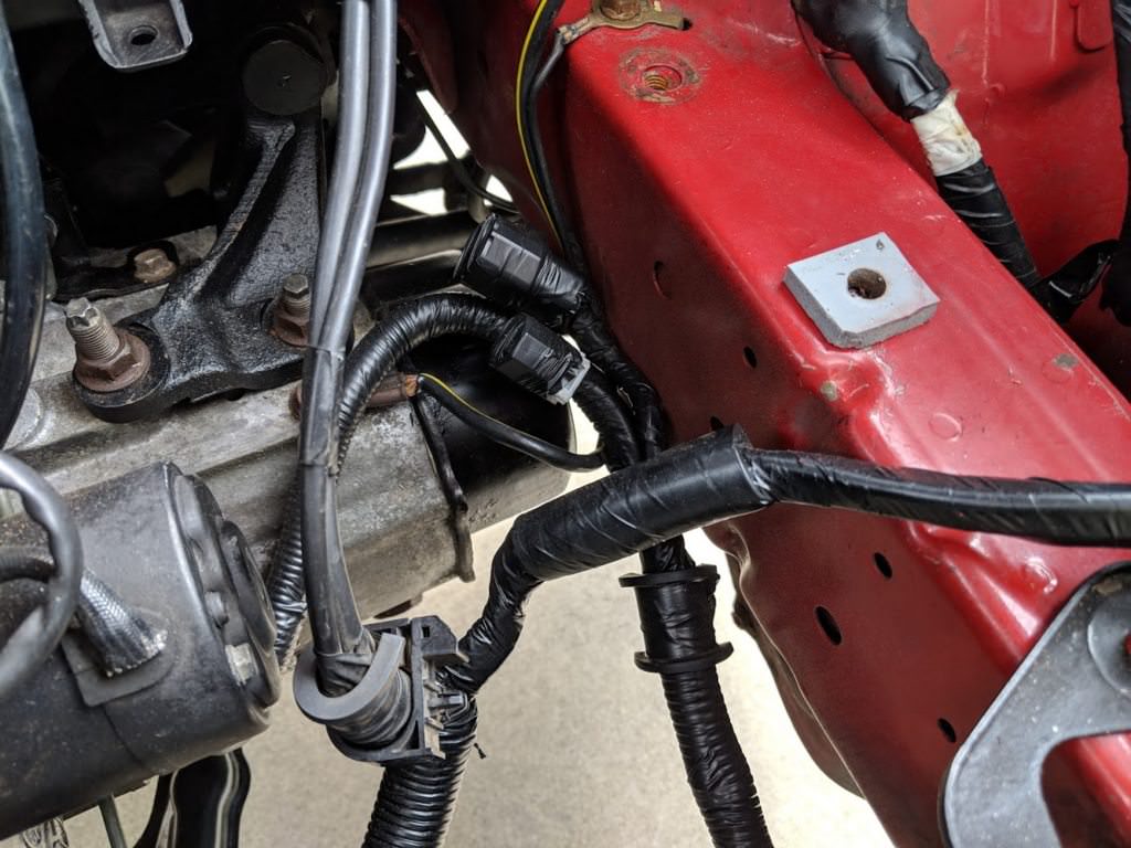
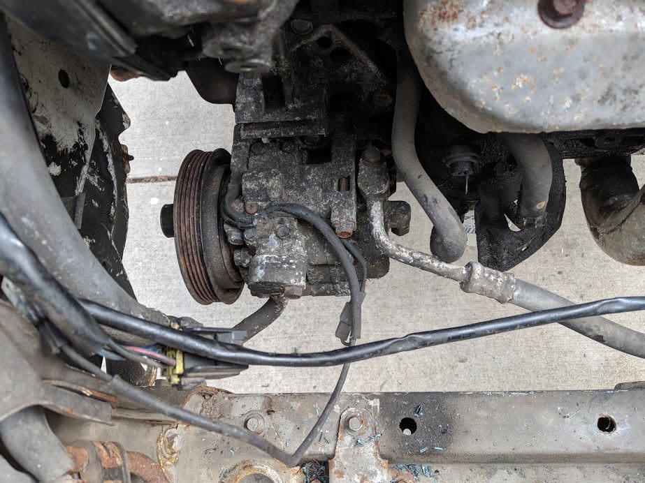
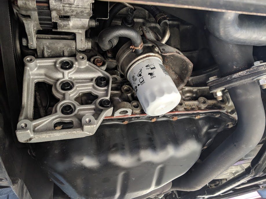
Disaster struck. I parked the car and saw a huge puddle of coolant on the ground.
Taking a closer look, and taking off the accessories, I could see coolant just pour
out from between the waterpump and the block. Well shit. I guess the engine overheated
enough to cook all the soft seals.
So yes, this is a page about replacing the water pump in a 1990 Mazda 323.
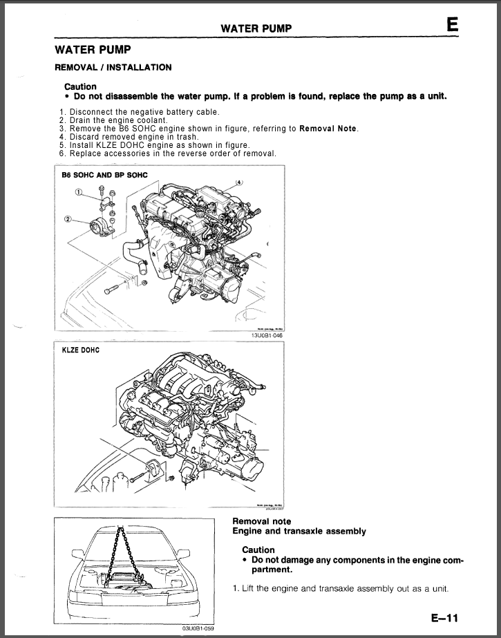
Let's consult the Mazda Factory Service Manual for what to do:
Oh. Oh dear. This just got interesting.
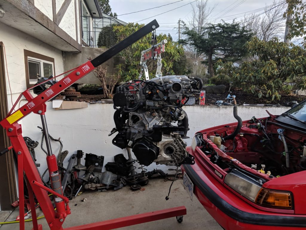
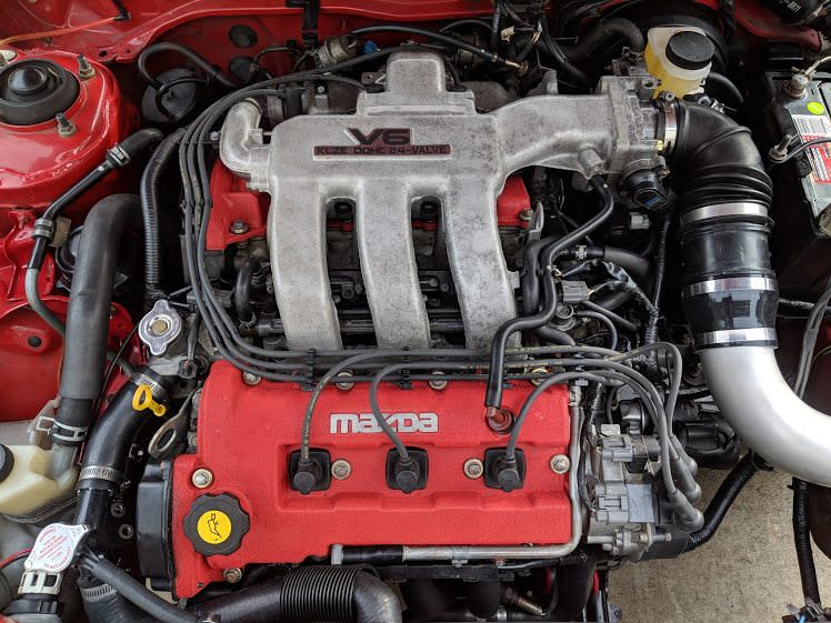
So, as you have all guessed, I am swapping a KLZE and a 5 speed standard into
the car. Basically a friend was given a trashed 1993 Mazda MX-3 GS (which had the
1.8L K8 V6) which someone had tried to swap a KLDE into and failed. It was then
left in a field for five years. Also in the field was a KLZE, which had been pulled
from a running MX3 after it was rear ended.
This means that I should be able to use the ECU, engine harness and lower motor
support from the MX3 to bolt the KLZE into the 323 chassis. I also need to use the
MX3 power steering, axels and maybe spindles, along with some other small parts.
Over the next few weeks, I'll try to catch up this thread on the progress, as I
started this all a couple months ago.
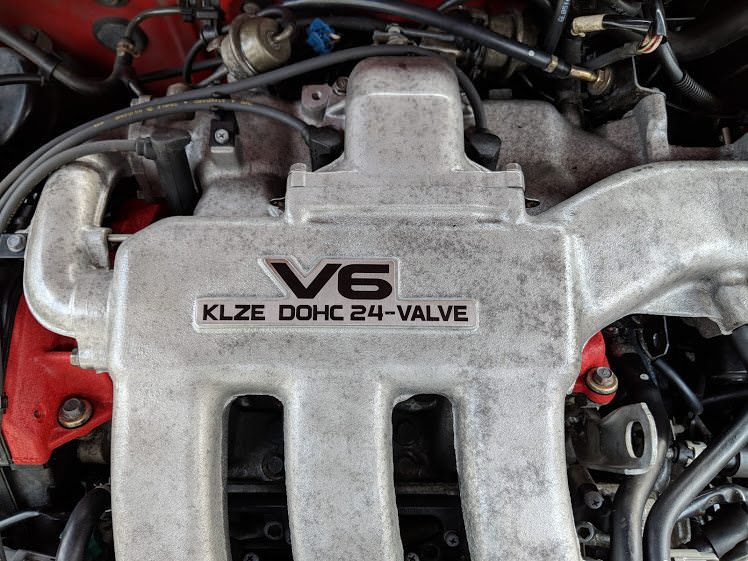
Basically, for the ZE, they added flat top pistons, different heads and cams, and
a better flowing intake manifold. It's considered the best of all the K series engines
and seems to be highly sought after for swaps. External dimensions of all the K
series engines are the same, so they are not too bad to interchange. The main differences
I have found so far is a third coolant sensor, a different distributor (external
coil) and the EGR system.
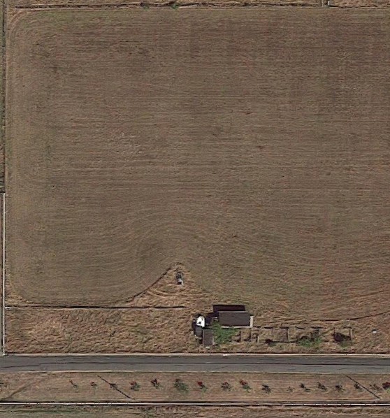
So where did we leave off? Oh right, Mazda told me I had to find a KLZE replacement.
Luckily I knew where one was:
Can you see it? Wasting valuable hay.
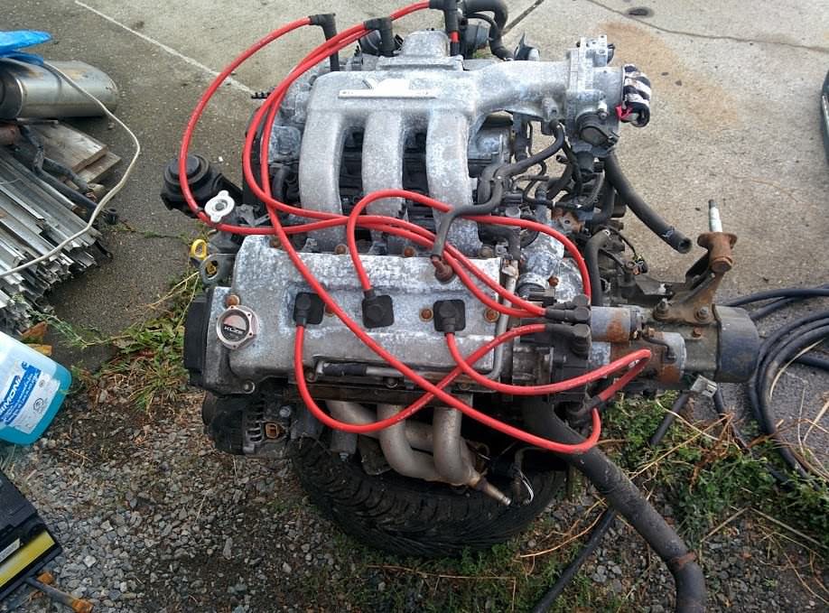
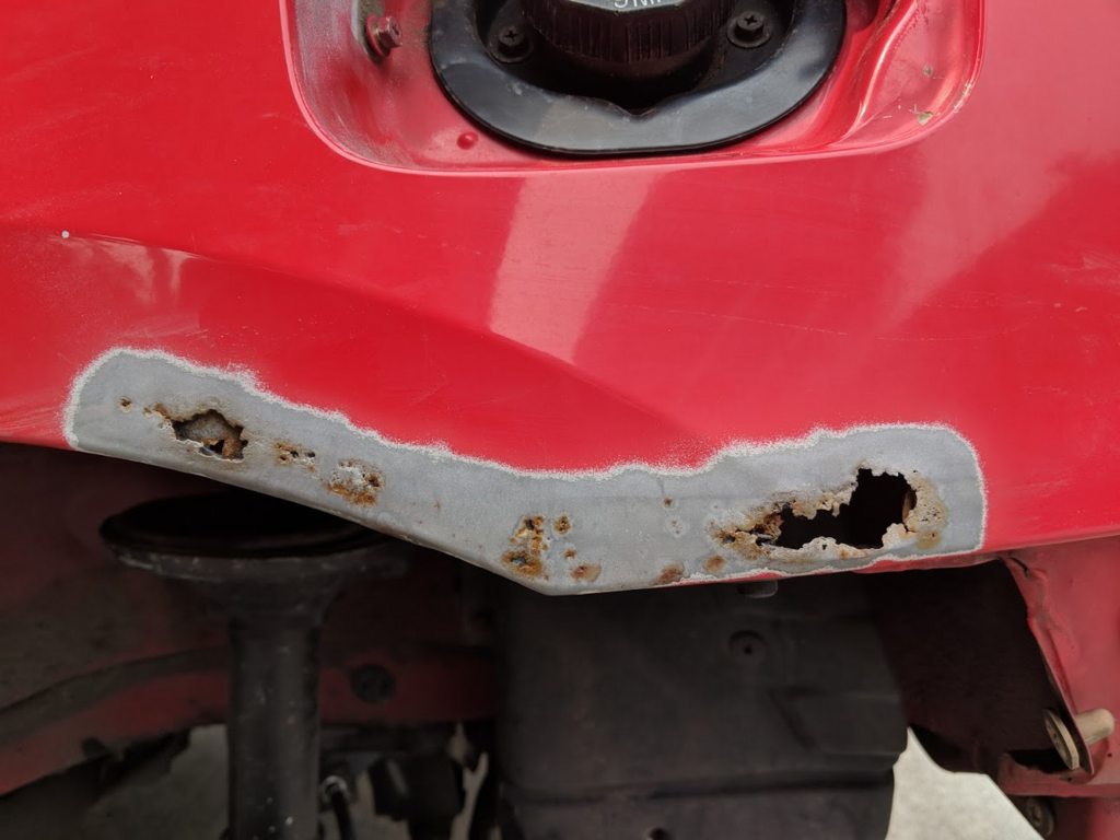
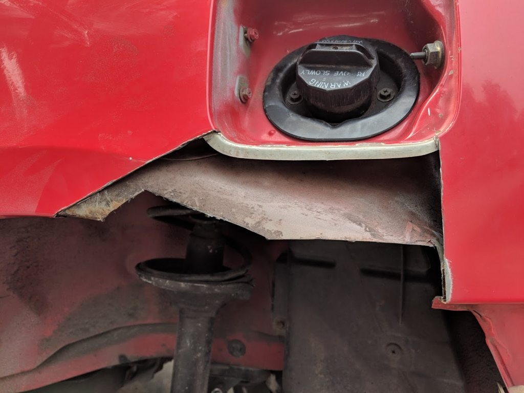
So much rust. So much corrosion.
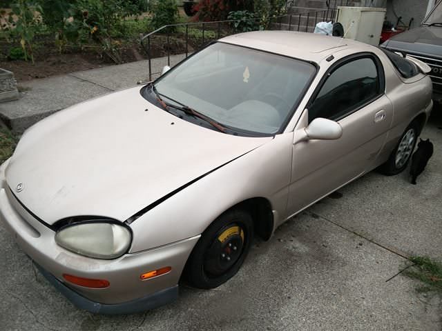
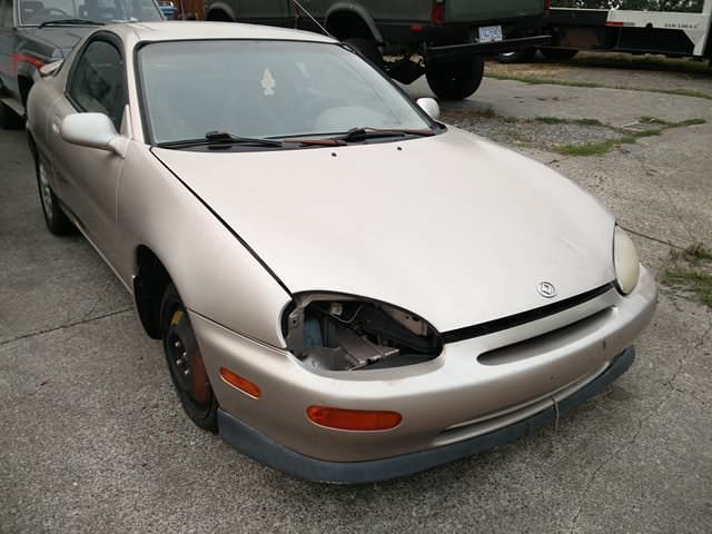
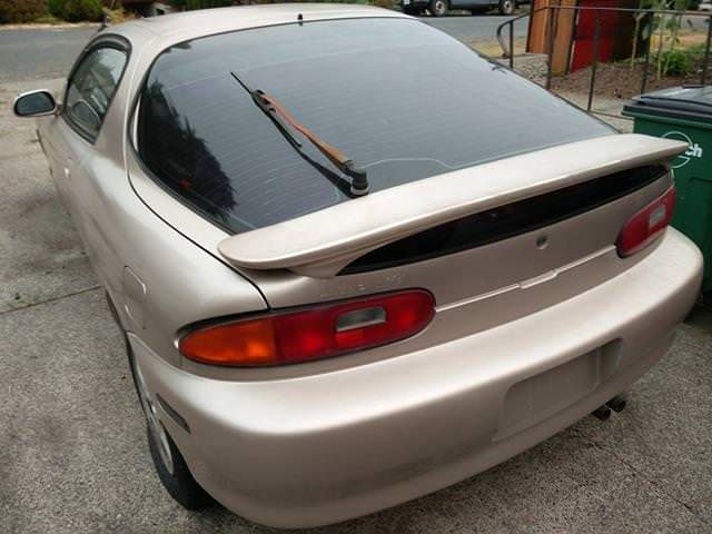
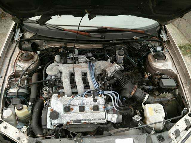
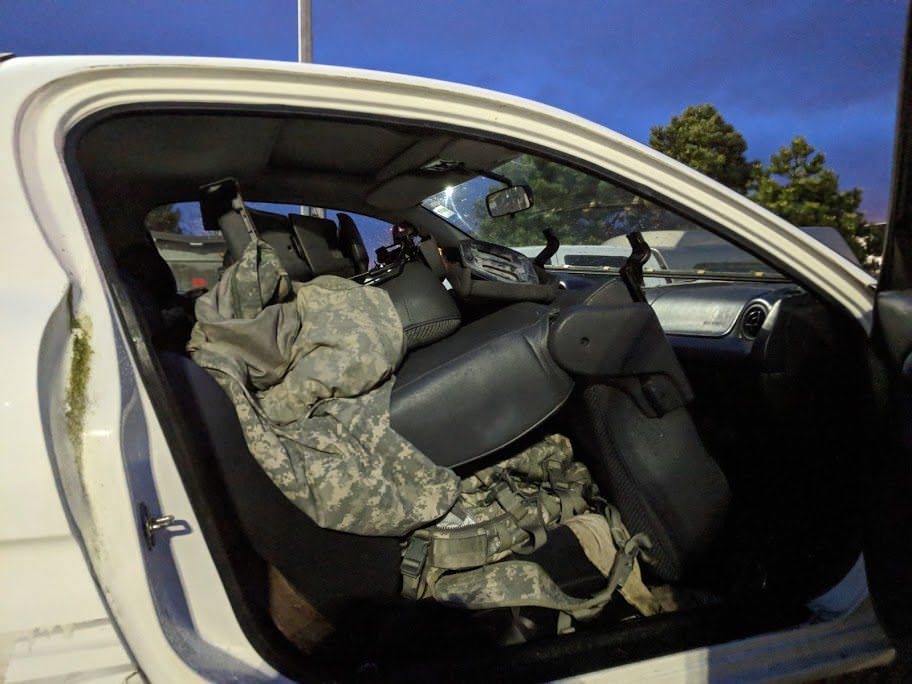
Let's take a look at the donor MX-3, who's V6 accessories we will need to scavenge:
Beautiful, one owner.
While it might be missing a light, it has two spare tires. Two donuts, what a deal!
Oh the smell. There was both mice and rats living inside the cabin. Even through
a mask I wanted to hurl. Hanta Virus, a bonus! Somehow they left the precious engine
wiring alone.
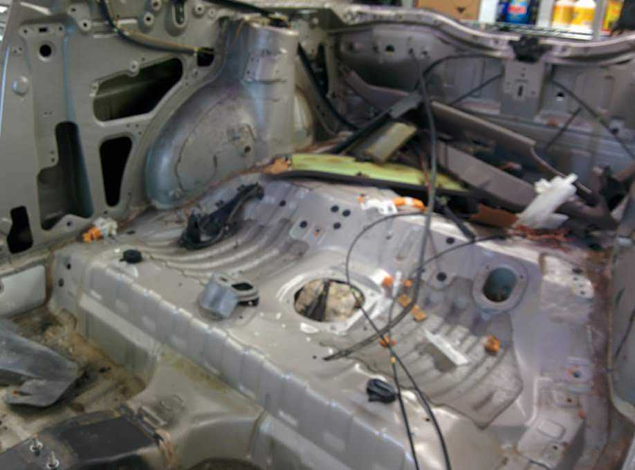
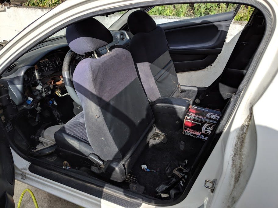
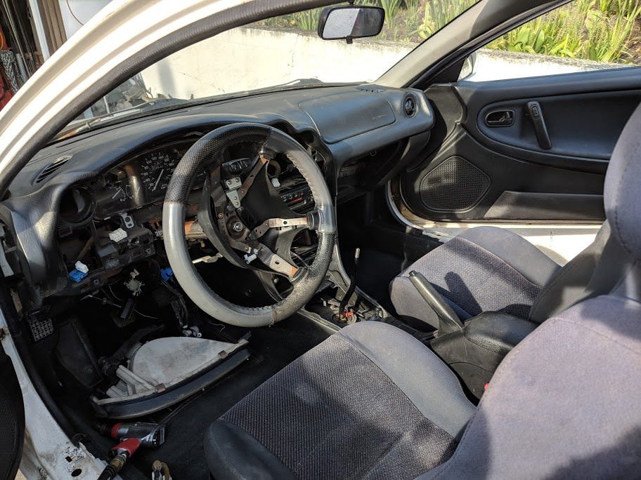
Time to strip the thing clean. Since I really didn't know what I was going to need
for the swap, I just started removing everything.
I don't think I've ever had to deal with a car quite as nasty as this one. Living
in a field for a few years had really taken a toll on the poor car. Inside and out
was covered in mildew, algae, white mold and black mold. At least six wasp nests
guarded the car, we must have gone through at least a couple cans of wasp-nuke.
The inside was also filled with rat and mouse droppings. As the interior panels
were removed, it became apparent that there had been a few nests inside.
The stink. My god, the stink in this car. Just absolutely disgusting. Rodent piss,
mold, who knows what else festered inside. I could taste it, through a full respirator
even. Absolutely unbearable. Even once the car was just a sheet metal shell the
smell was just as strong.
Luckily, aside from the sound deadening, the animals didn't appear to have chewed
through anything.
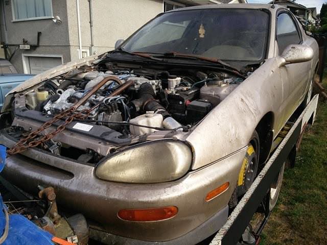
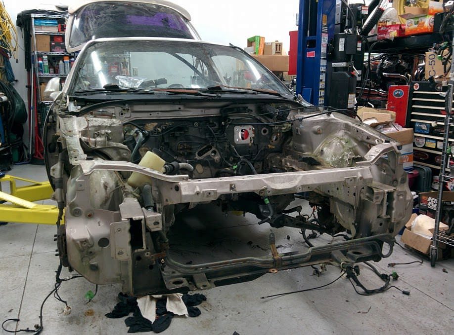
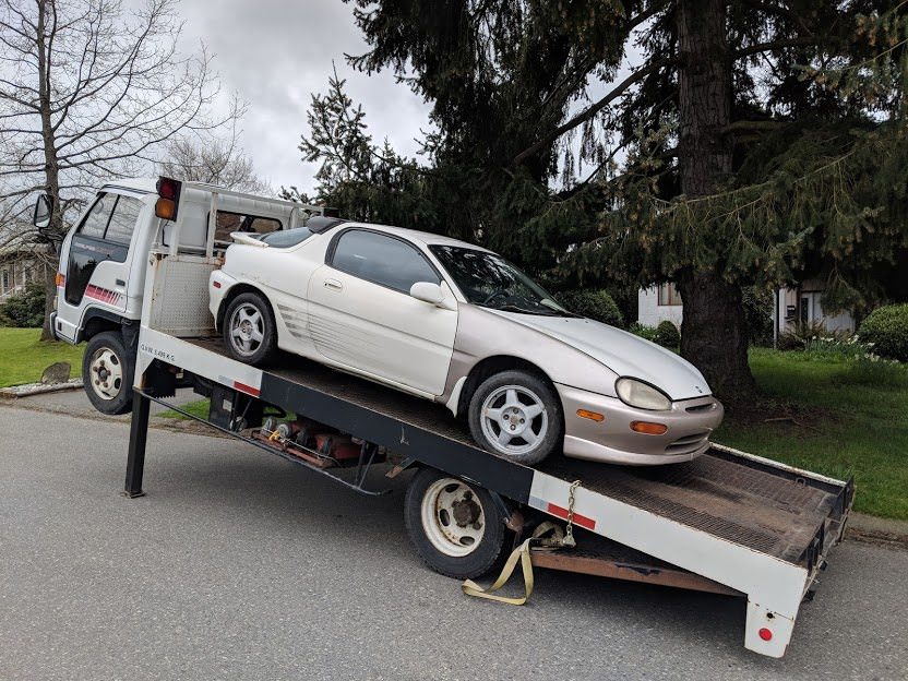
Car as it came on the truck:
As I said earlier, there seems to be an awful lot of conflicting information about
this swap. The general engine compartment and firewall is supposedly the same between
the MX-3 and the 323. The front and rear subframes are also supposedly interchangeable
- though bolts may be a little off. Even the 626 subframes have been swapped around
by others. In addition, the electrical systems are also compatible. While the engine
runs on its own separate harness, it does connect up to either body harness. The
MX-3 body harness has a slightly different electric cooling fan setup, as well as
a digital speedometer. Some guys have swapped the entire MX-3 harness over into
their 323.
Since I needed to get the car scrapped and I didn't know exactly what I would need,
I did the logical thing and took everything that was bolted to the damn chassis.
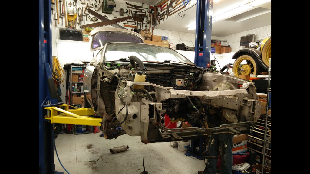
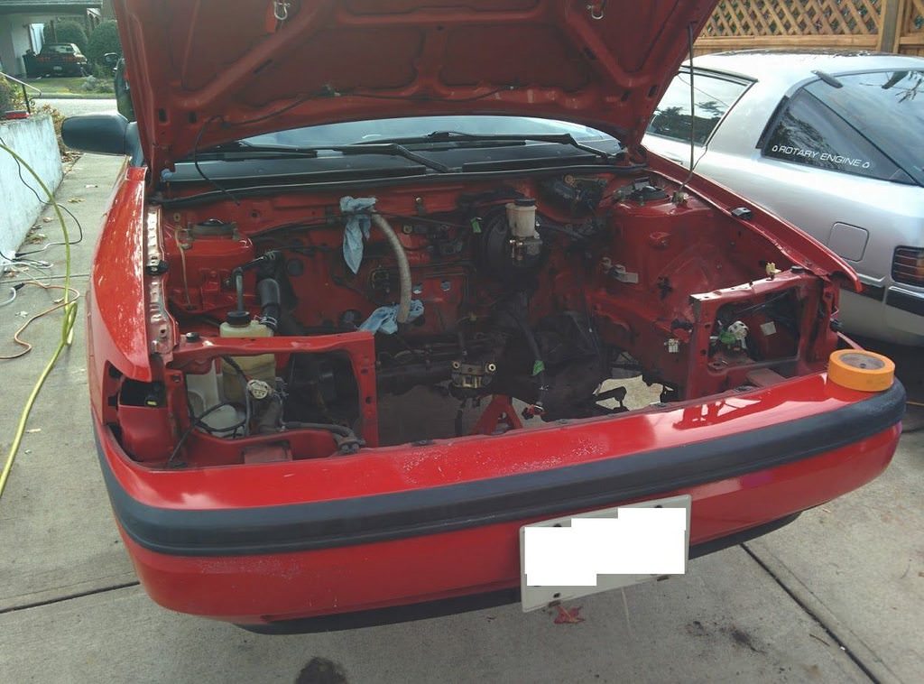
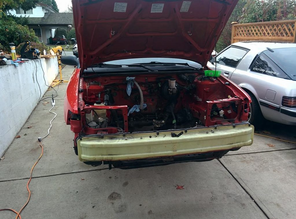
Engine removed, and subframes held on with only a couple bolts:
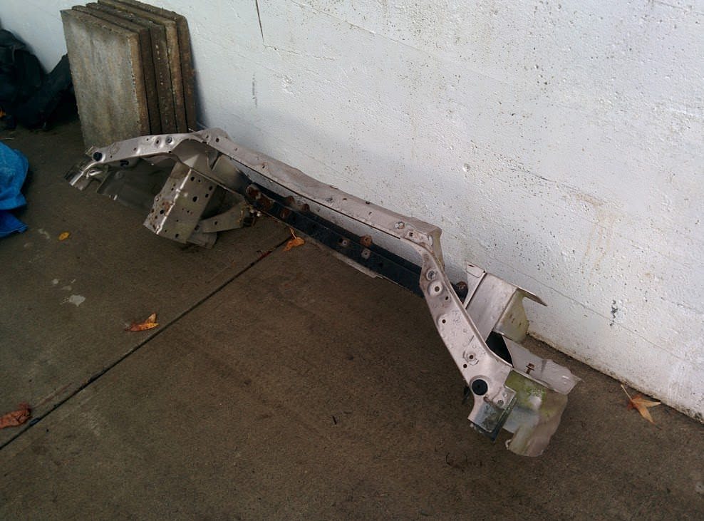
I even cut off the front end, as I may need to steal the radiator supports:
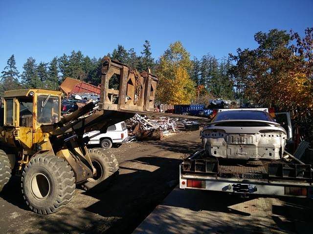
After it was stripped, it got loaded back onto the ramp truck to take to the scrap
yard.
Soon to become a brand new KIA.
Guess how much steel I left on the car?
$23.50 CAD. Yeah, pretty stripped.
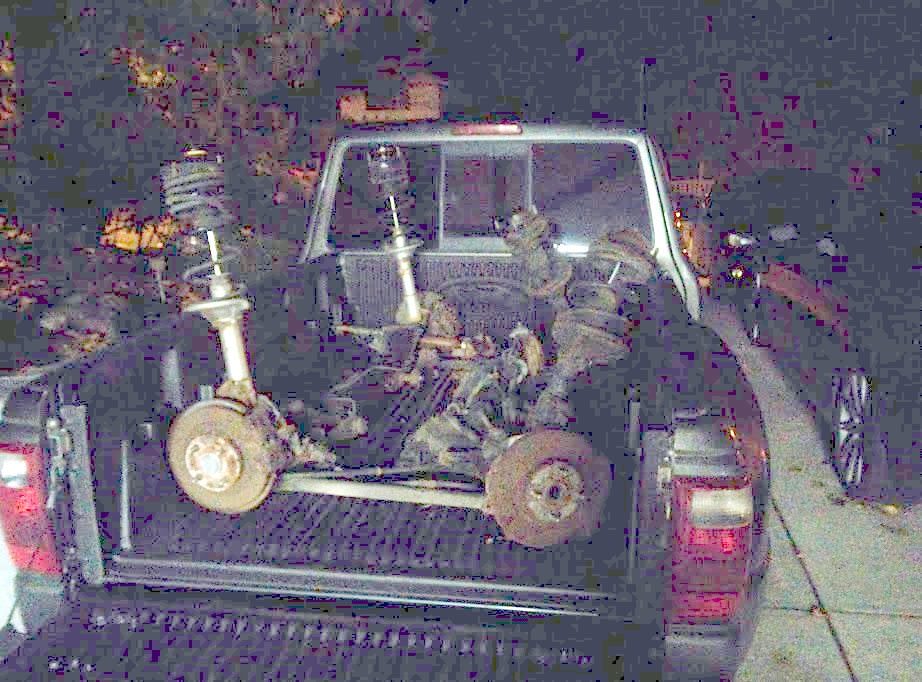
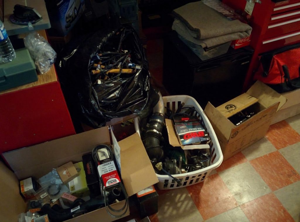
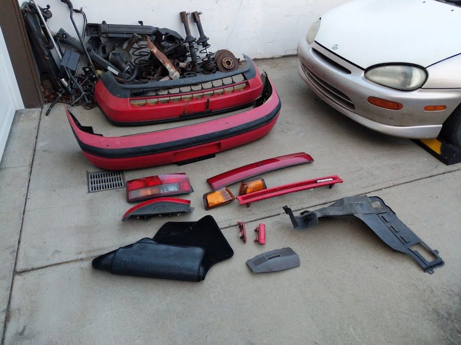
Since the car was now scrapped, I was left with a mountain of parts. It seems
that once you remove the damn things, they occupy twice as much space as the car
itself. I did what any normal person would do and spread them thoroughly around.
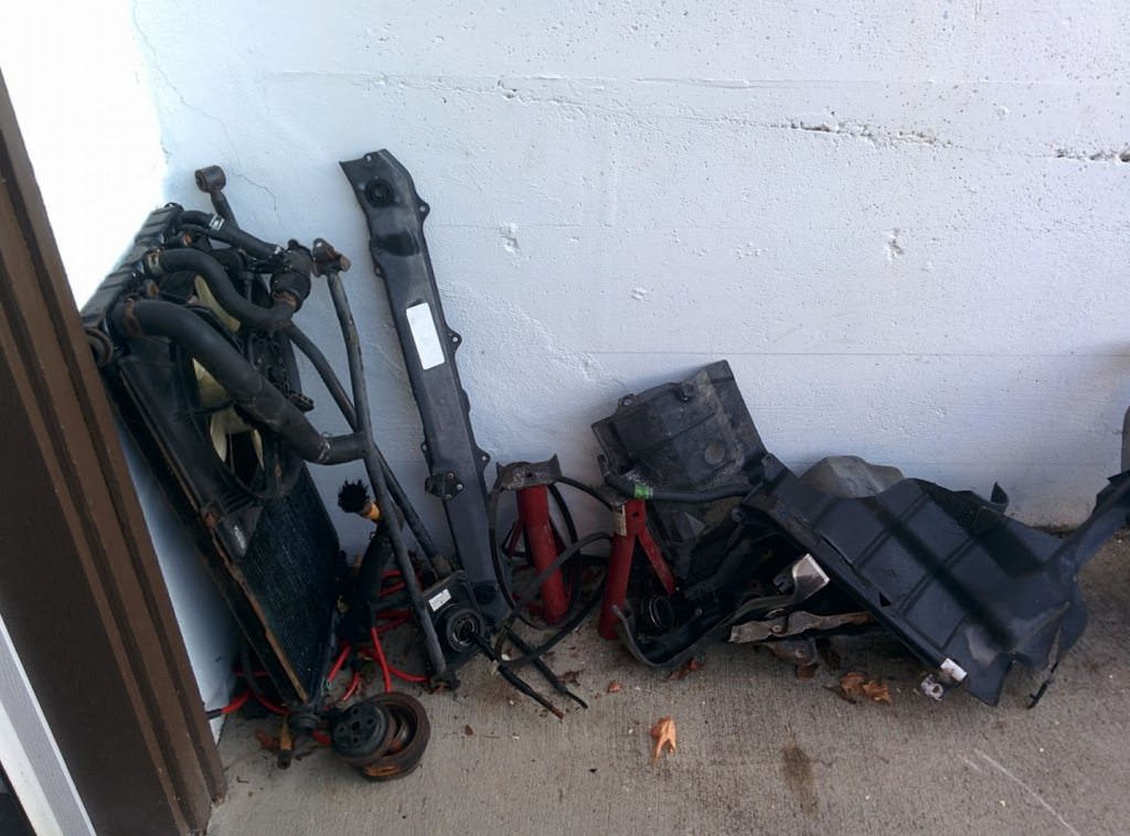
MX-3 Radiator, rad supports, shifter linkage and some splash guards.
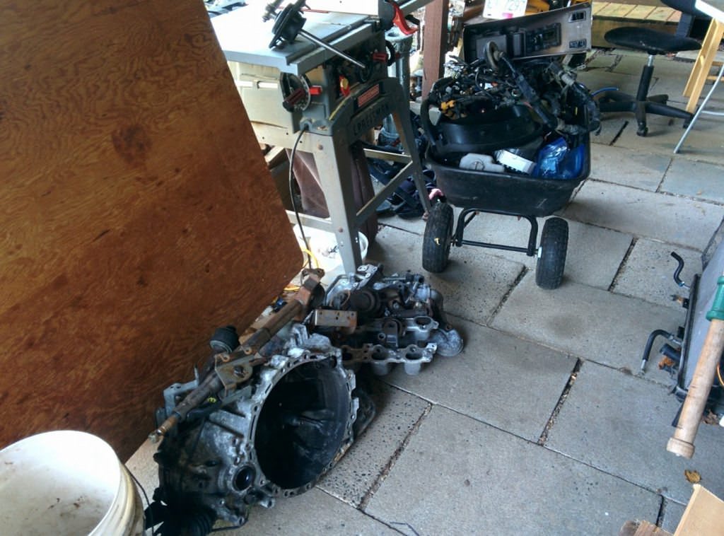
MX-3 5-speed, adjustable steering column, intake manifold for a K8 (useless) and
an entire cart full of interior pieces, gauges and whatnot.
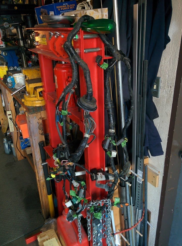
Box full of RockAuto goodies, entire MX-3 body harness, laundry basket full of original
KLZE parts, box full of K8 cams and some axles which won't fit, but would have cost
more to ship back in boxes.
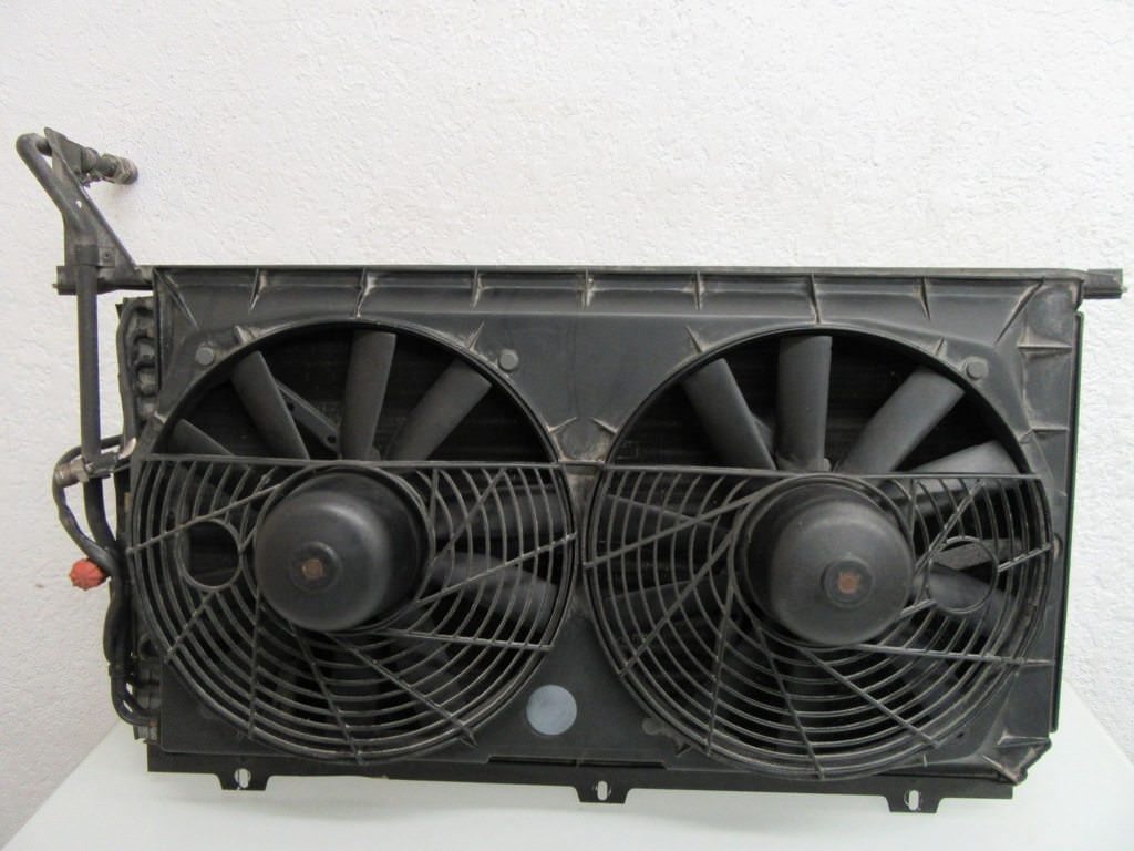
Dodge Neon radiator, Mercedes Benz front aux fans, VAF, pedal box, cruise control
and fuel sender. Also, a duck.
MX-3 K8 engine harness. This one is an early 92/93, so it has the three coolant
sensors wired, just like the KLZE has. This means that technically the ECU driven
fan signals should work.
Now, you might be asking why is there a Dodge Neon radiator. Well, apparently they
will fit quite nicely inside the front nose of a 323 to give me extra room for the
V6. A few weeks back, I was able to tag along to the mainland for free, because
my pops had business meetings. Normally it would cost ~$80 each way to take the
ferry. I spent the day in rainy Chilliwack BC, at the Pick a Part. Its one of the
last you-pull junkyards around, and does cheap, flat rate pricing on all parts.
I loaded up with two bags of tools, an electric impact, a drill and an electric
sawsall. Stupidly useful to bring a saw to the yard, I was able to cut out a rust
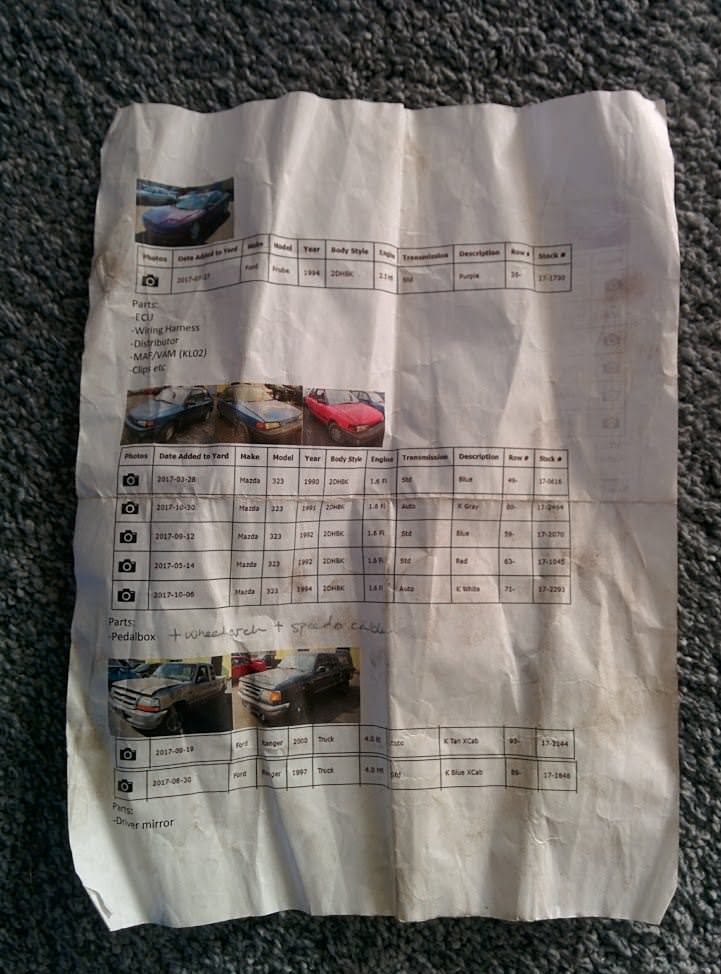
patch panel from one of the 323 wheel arches. I knew that I would be pressed for
time and I would probably get excited and forget some stuff, so I made myself a
double sided list with what I wanted, where it was in the yard and a picture of
each car.
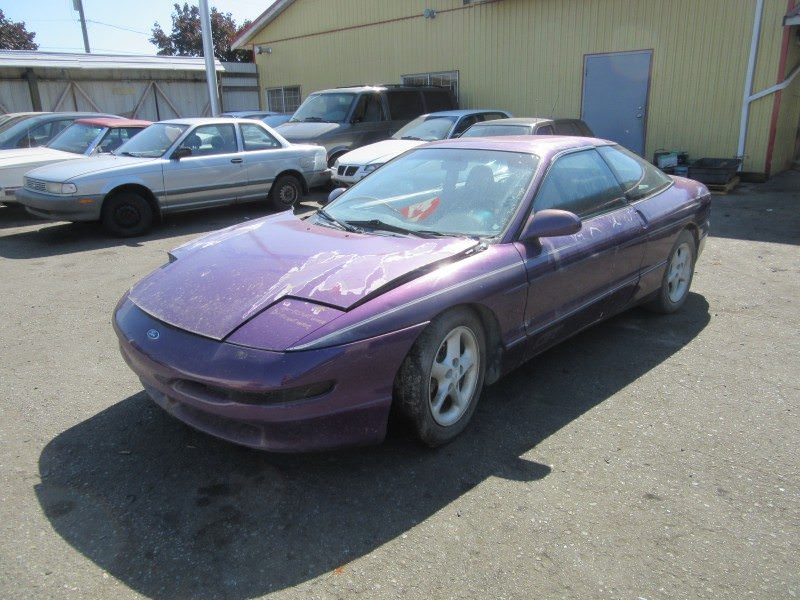
I got to the yard at 10am. First stop:
1994 Ford Probe. Came with a 2.5L KLDE engine. Basically the exact same engine as
the KLZE, minus flat top pistons, heads, cams and intake. I grabbed the ECU, a KL48
(same as the KL55, just Feeerd.). I also took the KL02 VAF (same as the 626, MX6
etc), the engine wiring harness, distributor and the broken clips from my engine.
I also snagged the fuel filter bracket, since the 2.5L uses a bigger filter than
the 1.8L.
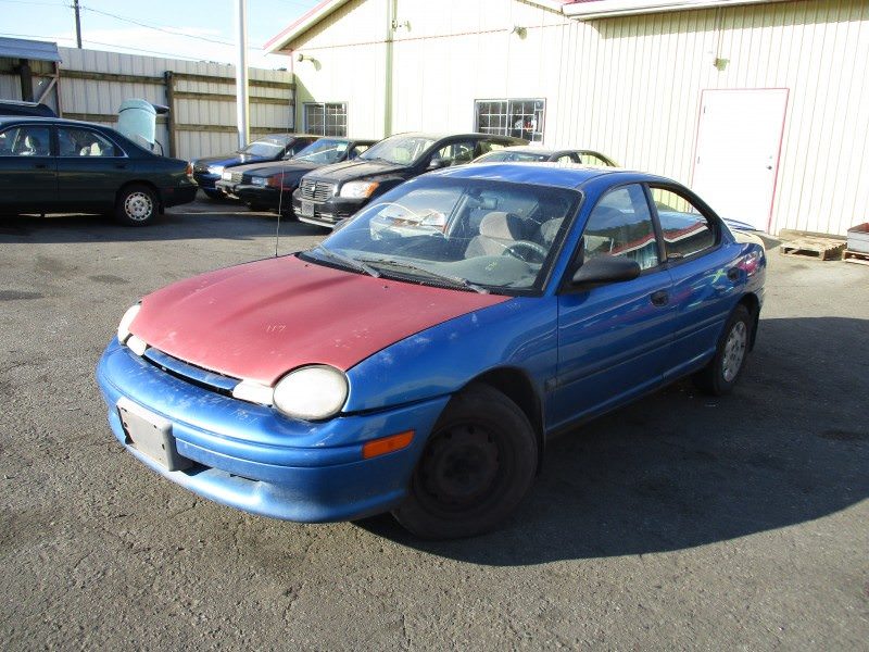
Next it was off the the *urgh* Dodge Neons *shudder*. Jesus, there was a lot of
them to choose from.
I honestly can't remember which car I pulled the radiator from. It was between 1997-1999
2.0L SOHC. I took the only aftermarket replacement radiator in the yard, figuring
it would be in the best shape. Interestingly, all the other Neons still had their
factory radiator.
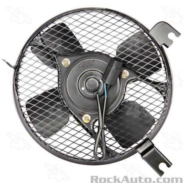
Now, I needed a fan to go with the new radiator. I wanted something that would push
instead of pull, so I could mount it in front. That seemed to leave me primarily
with supplemental AC booster fans. I nabbed a neat small fan out of some 1980's
Toyota. I think it was a Corolla fan, judging by RockAuto. It is small and all metal,
so it might be a good option. It is only a single speed though. Technically the
manual transmission 323s and MX-3s had a single speed fan, while the automatics
had a two speed. I am not sure if I will really need a two speed, given I am swapping
a manual in.
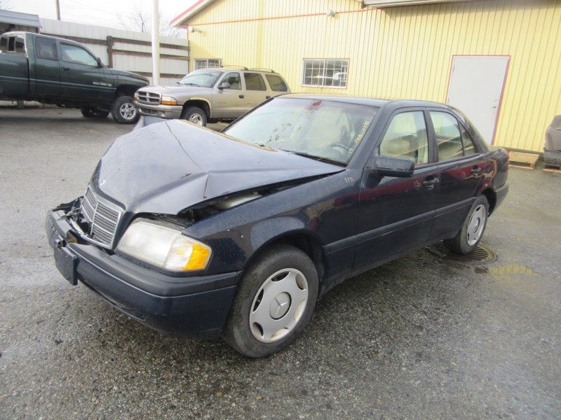
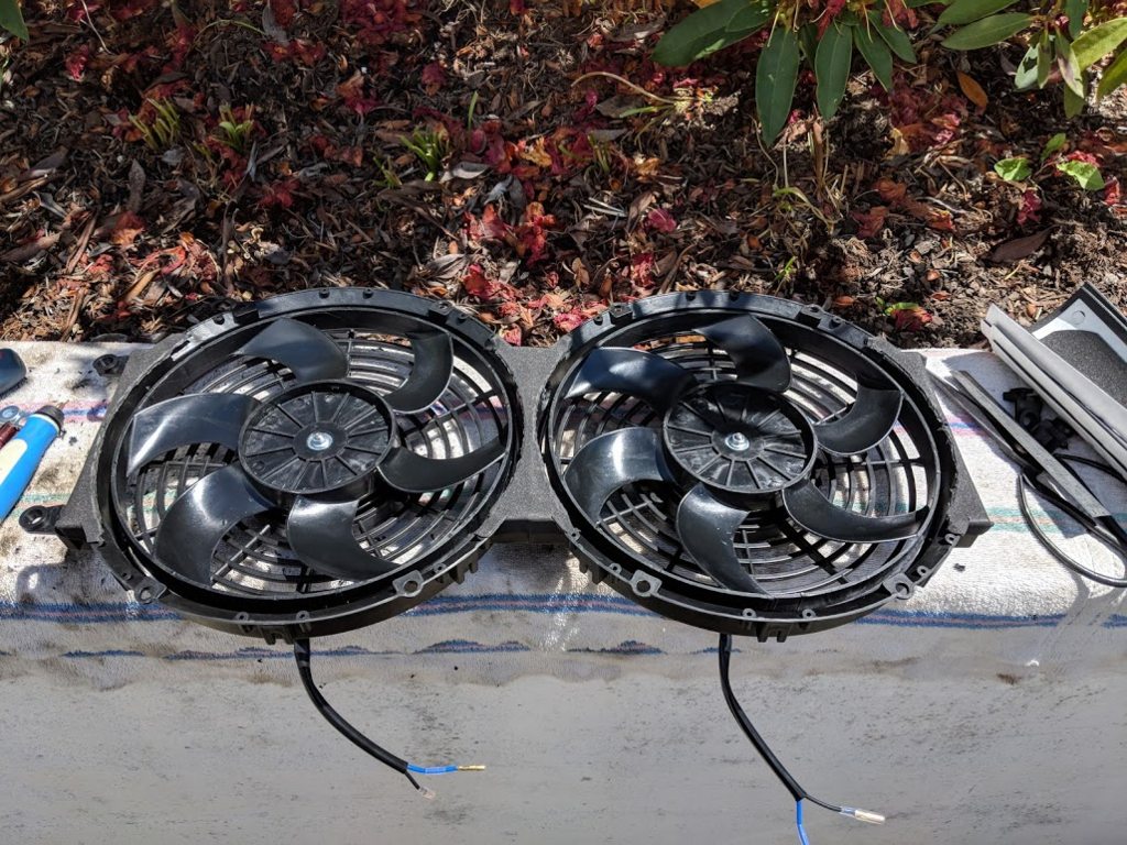
I also nabbed the fans out of a Merc, a C200 something I think. Pretty serious fans,
when I tested them with the M12 battery on the yard, the were pretty much hovering
off the hood. Oddly enough, the two cars which had them both had the passenger side
not work. I looked at the wiring and they were both two wires, in parallel. Seemed
odd to me, I figured at first maybe one was low and one was high. Part numbers of
each fan motor was the same as well. I swapped the bad fan out in the yard with
a good one, so I ended up with a working dual setup. If I end up using these, I
will wire up one fan for low and two for high.
After snagging a Volvo fan and relay setup for a friend, a F250 IDM and some other
things, I finally had my way with the 323s in the yard. Look at these poor things:
Oddly enough, there were a few standard transmission 323s. I snagged the pedal box,
since Mazda EPC shows that it had a different part number from the MX-3 one, a cable
driven speedo gear assembly, the manual transmission interior trim and shift knob,
and some other small bits. There was one with a brand new ignition switch, so I
took that as well. I also used the sawsall to cut out a rear wheel arch, since mine
has some rust. I'll either weld it in or use it as a template.
All told, I spent six rainy hours in the yard and $300. Not a bad day.
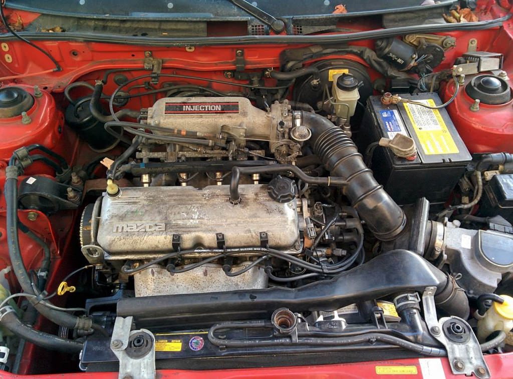
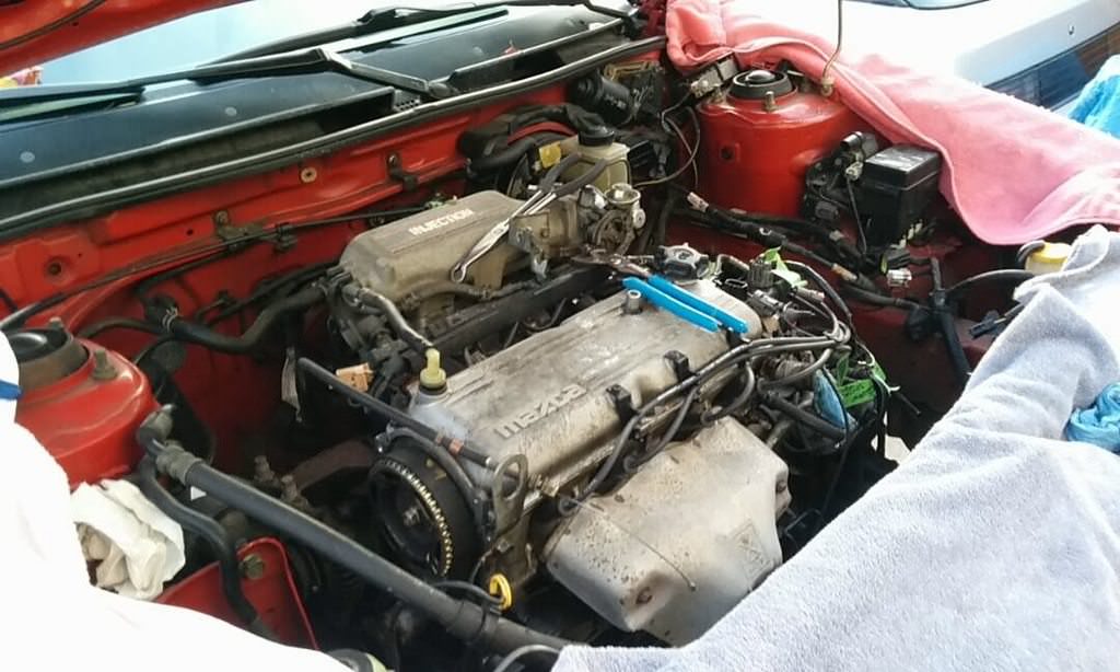
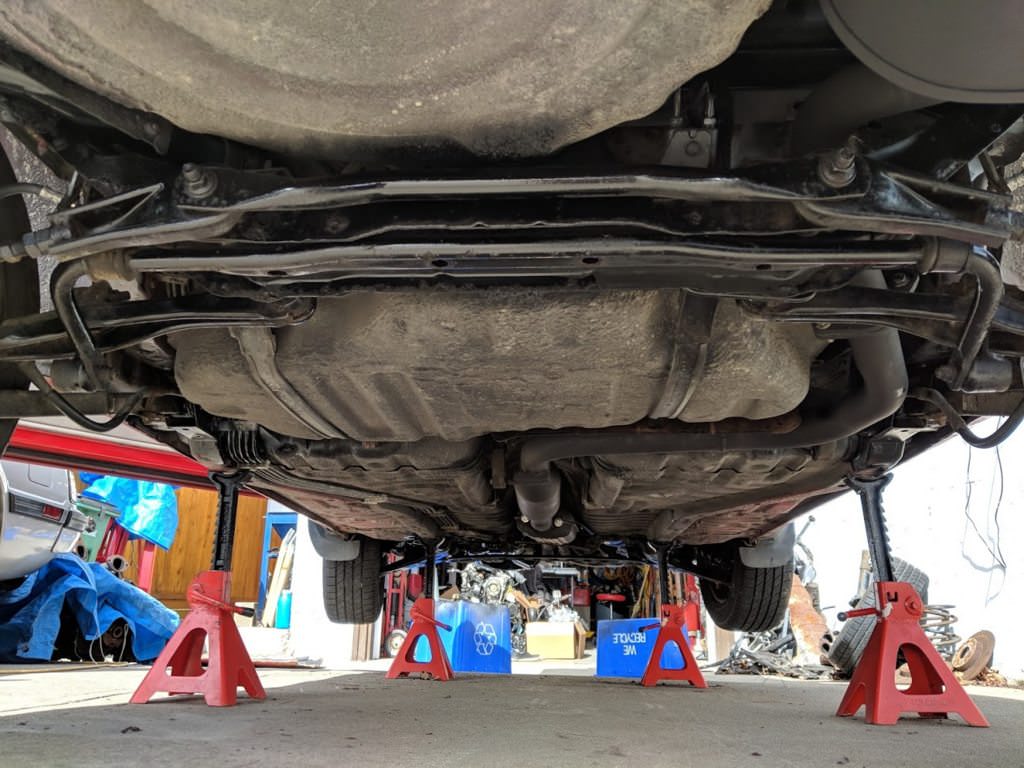
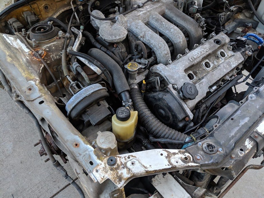
Next, it was time to pull the old B6 motor. Shuffled some cars around and got
the 323 up on jackstands.
Look how tiny it is. Barely fills the engine bay.
Starting to disconnect everything. Took about two hours to label and disconnect
after work over a couple days.
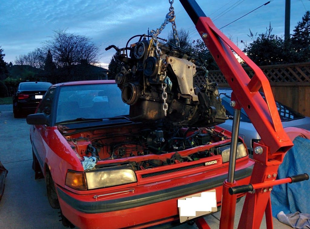
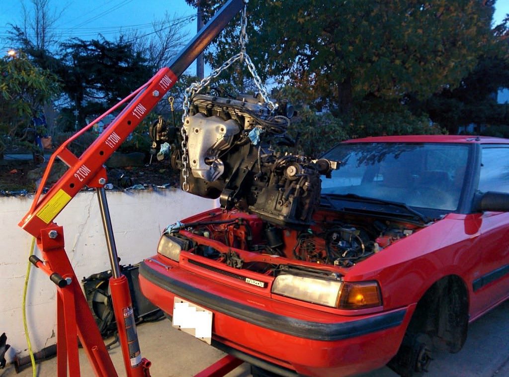
Lets pull the engine:
There, that's better. All told, it was pretty uneventful.
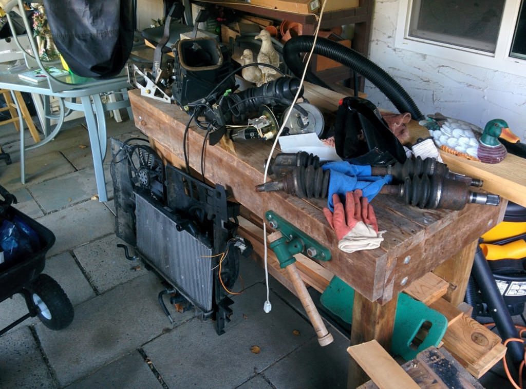
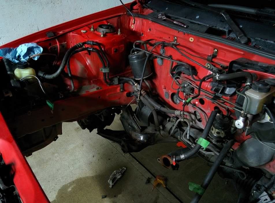
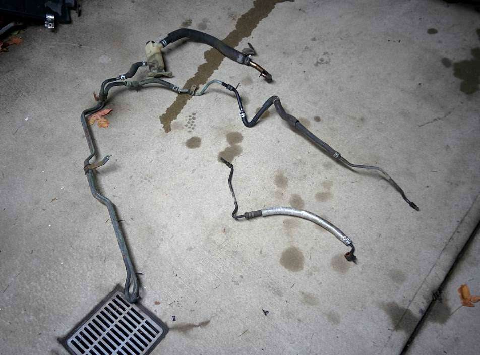
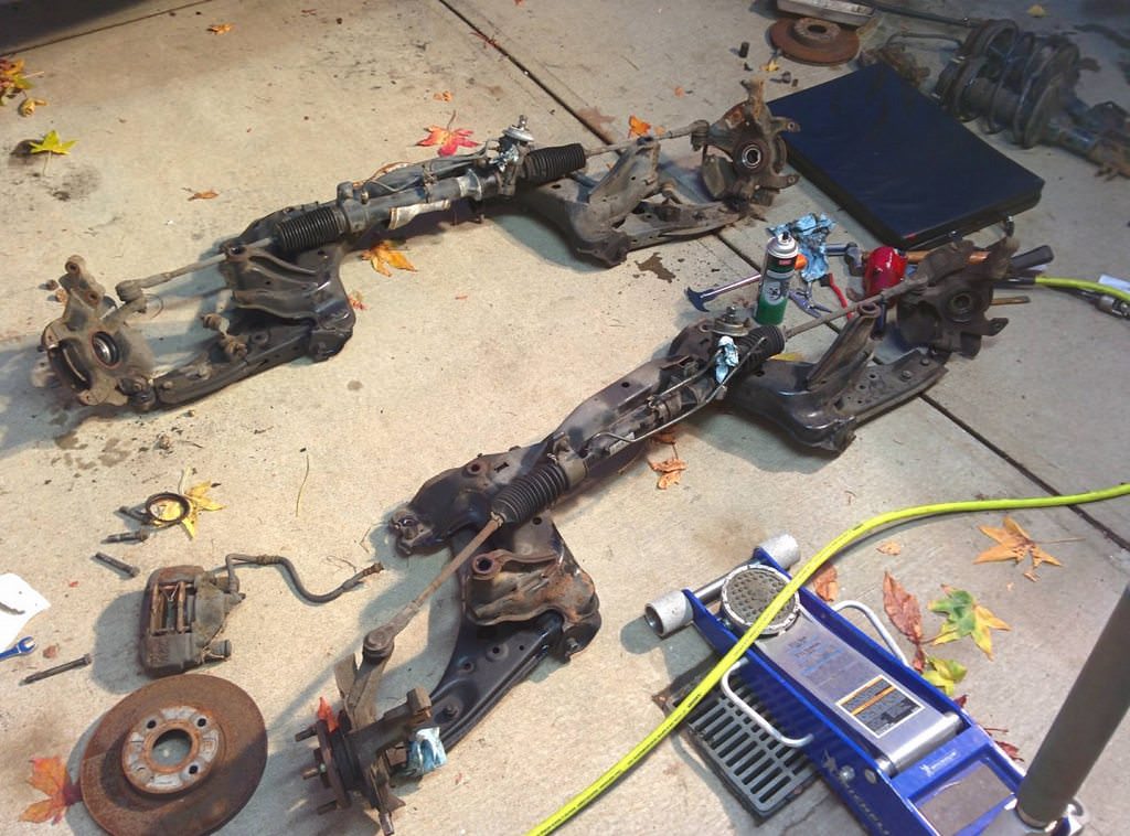
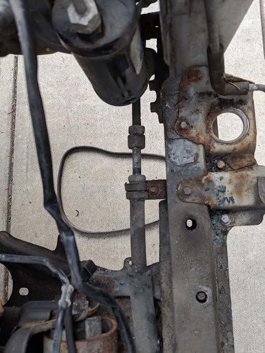
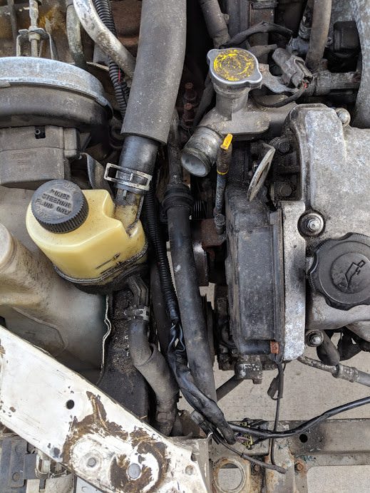
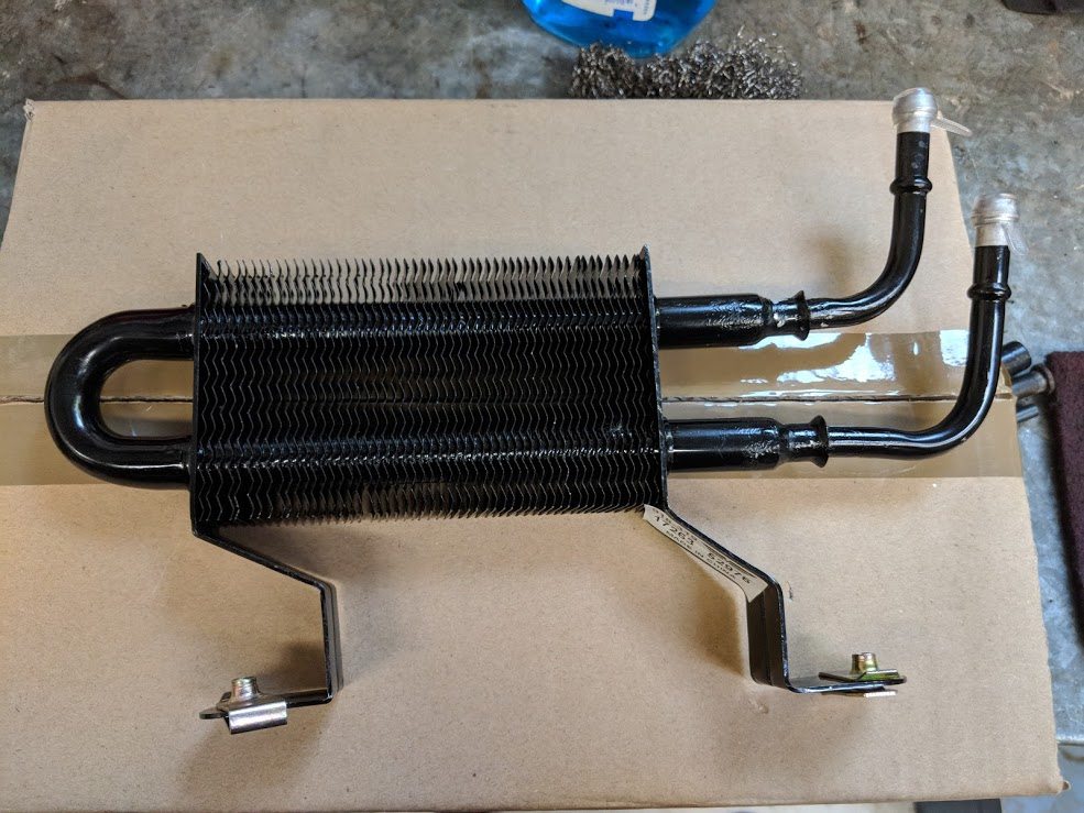
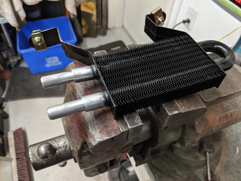
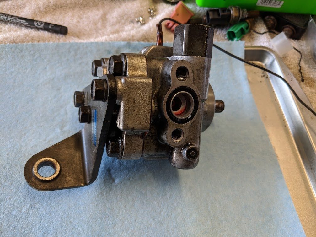
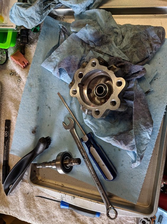
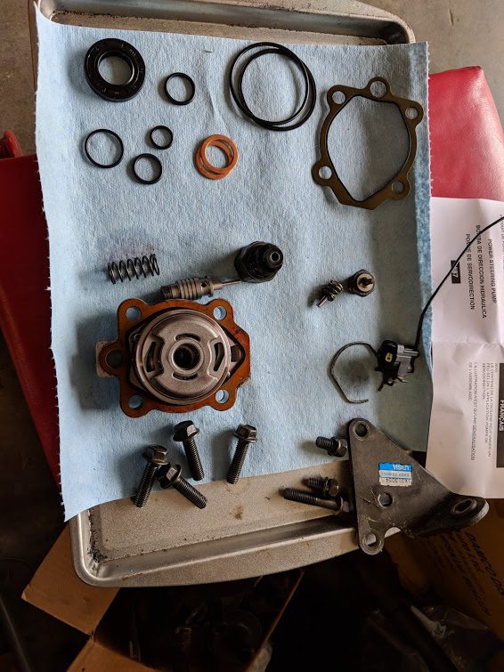
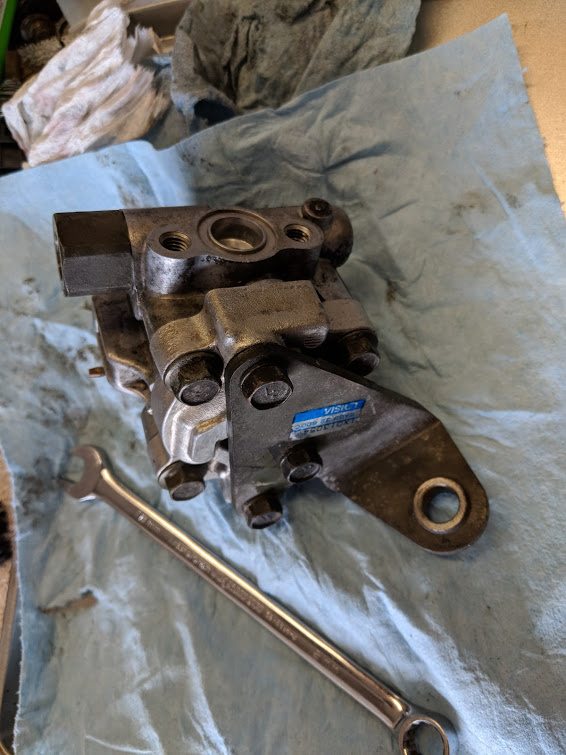
With the engine out, I could compare the 323 power steering system to the MX-3 system.
The MX-3 rack has a quicker turn ratio, so I would prefer to use that. I also need
to use the MX-3 power steering pump.
The 323 power steering looks like this:
and the MX-3 stuff:
I will make a hybrid with the MX-3 rack, the 323 cooling loop, the MX3 tank, the
MX3 pump fittings and the hard/soft line from the cooler loop to the MX-3 rack hardline.
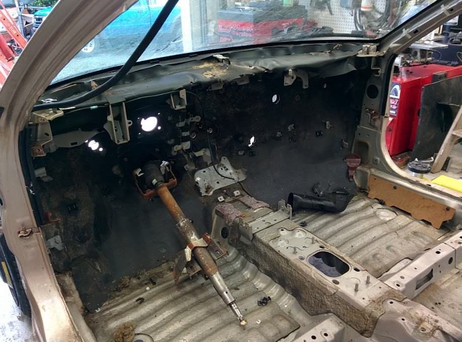
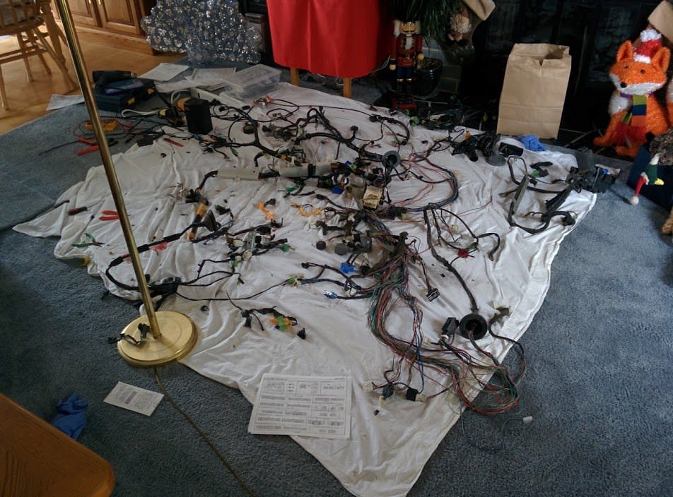
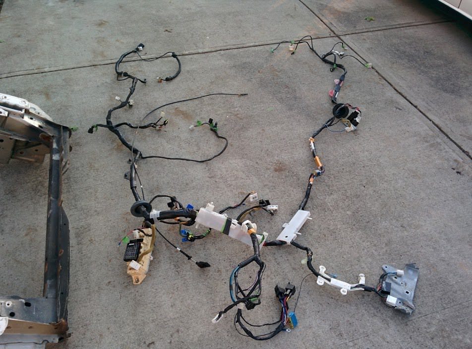
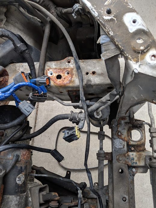
Next, it was time to tackle the wiring harness. I hauled the body harness out of
the 323 and started going through it. I had to convert the auto harness to a manual
transmission, as well as matching up the engine harness interconnection plugs, as
well as adding some of the 626 features, like the windshield washer fluid level
sensor.
I wrapped the finished harness using PVC wiring harness wrapping tape. Way nicer
than electrical tape for this.
Interestingly, since this was an early 323, the automatic trans computer was separate
from the ecu. This meant that some of the signals, like the speed sensor and the
brake switch first went to the auto computer and then to the ecu via different wires
on the auto computer plugs. I had to cut and join the two of them to bypass the
auto computer plugs essentially.
I also had to strip out the clutch pedal starter switch and the clutch pedal switch.
Stole the wiring for those from the MX3 harness, running the lines to the appropriate
places. The transmission neutral switch is dealt with by the engine harness. The
reverse lights were in the body harness. I cut the plug off and spliced into the
appropriate wires in the auto trans connectors for these.
Everyone complains about the electric fans not working after changing the engine
harness. I think I know why. The body harness for a manual trans 323 and a manual
trans mx3 have the same circuit for the fans, but where they join to the engine
harness is different. Same goes for the speed sensor, and the rear defrost signal.
Had to swap around a few pins on the engine to body harness plugs.
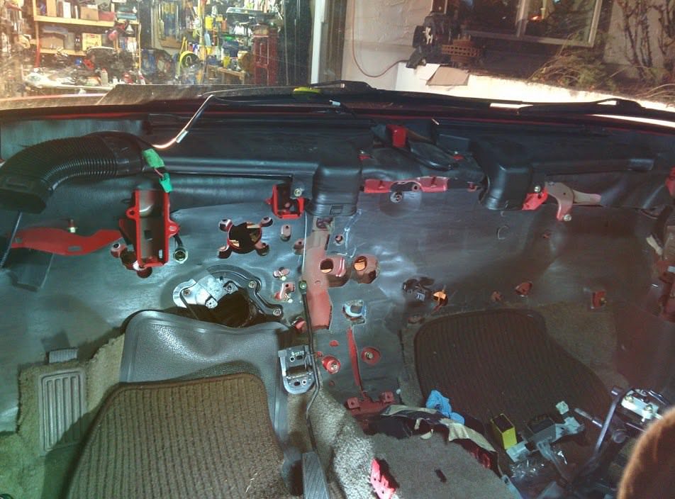
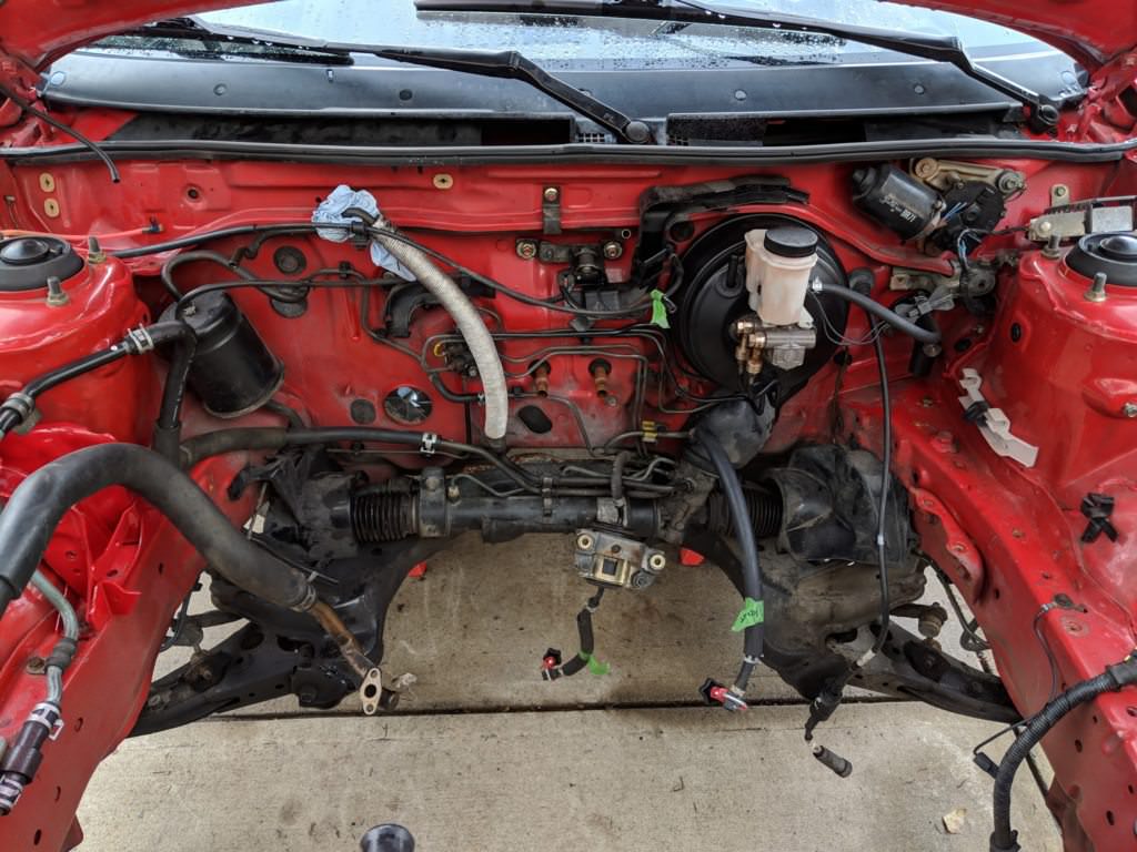
Back into the body it goes. It looks so empty in here.
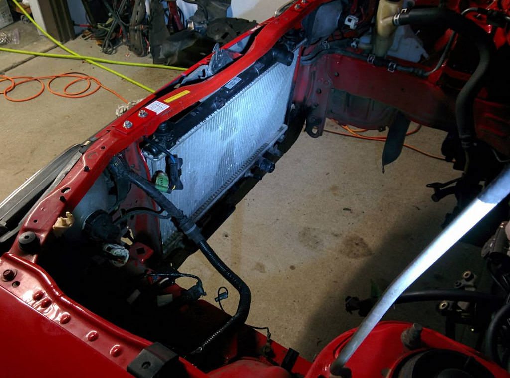
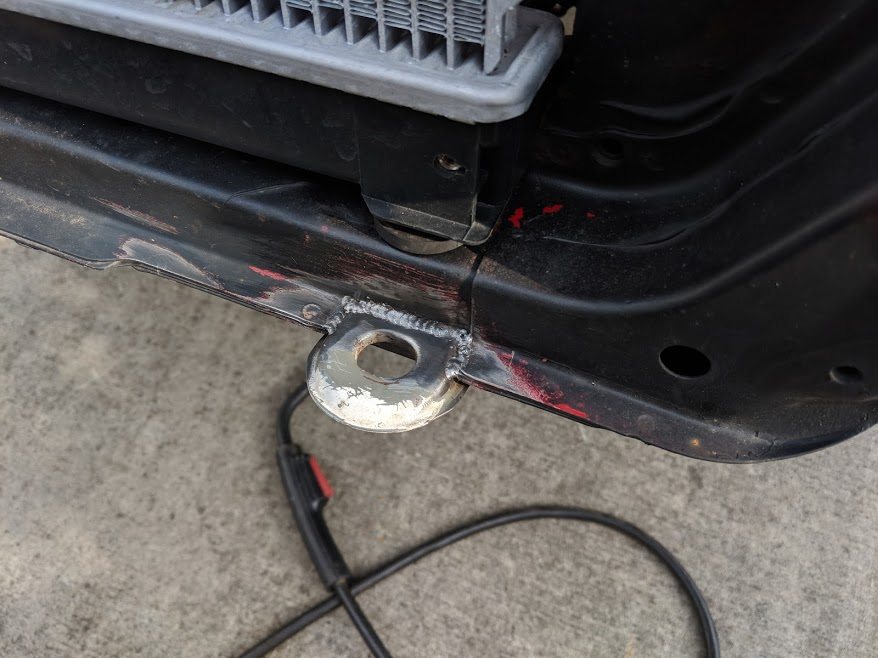
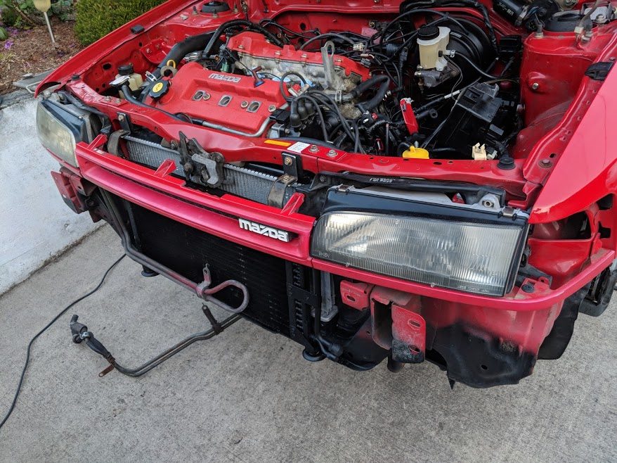
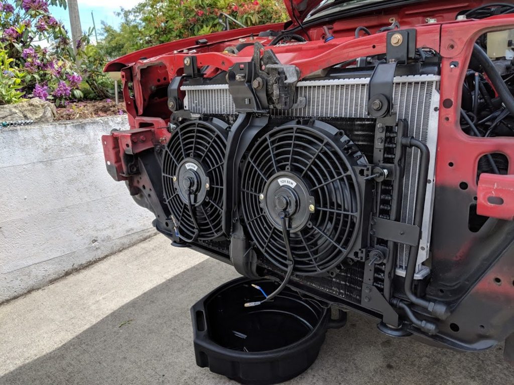
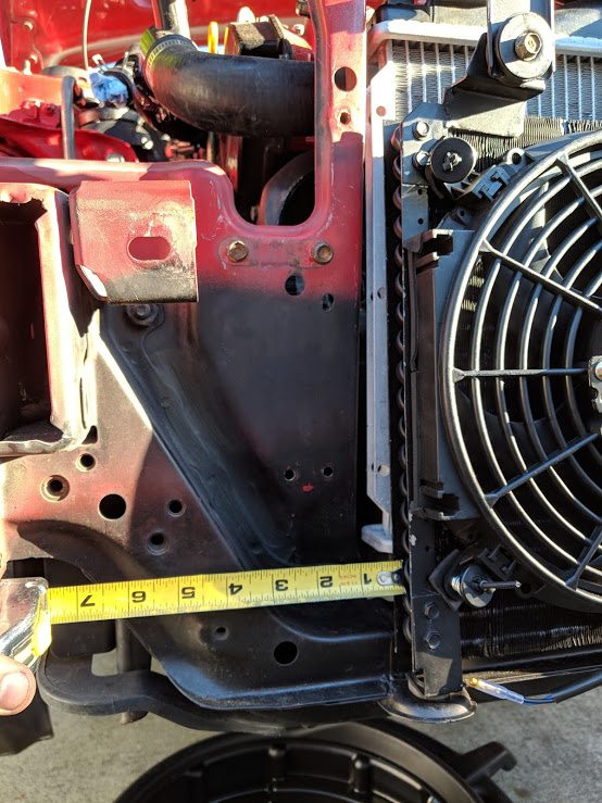
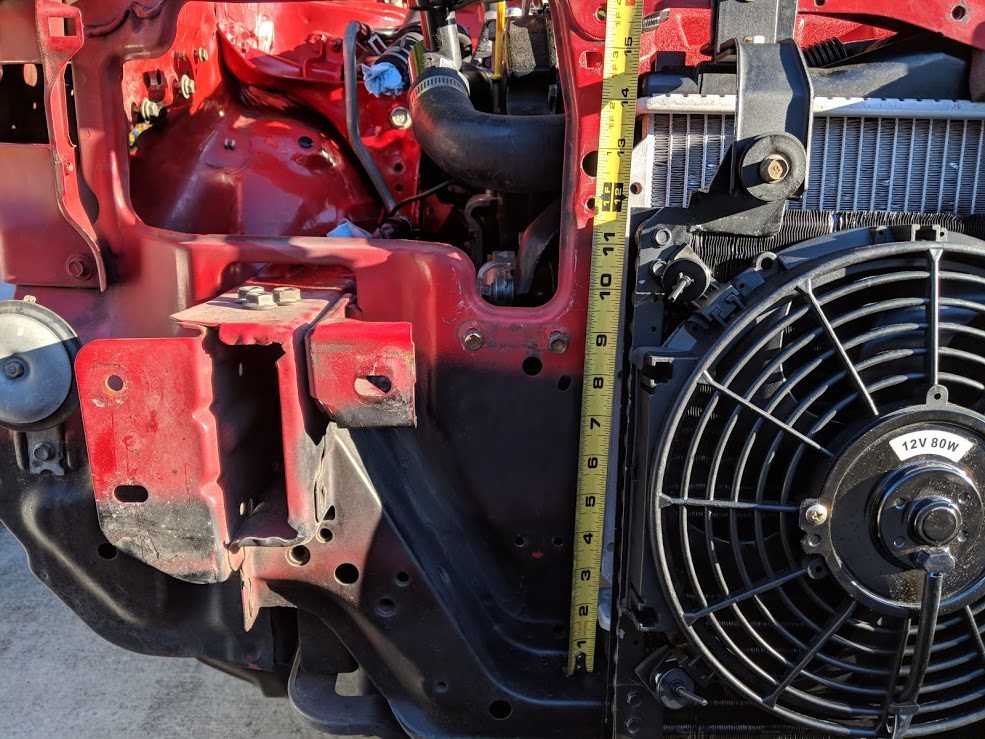
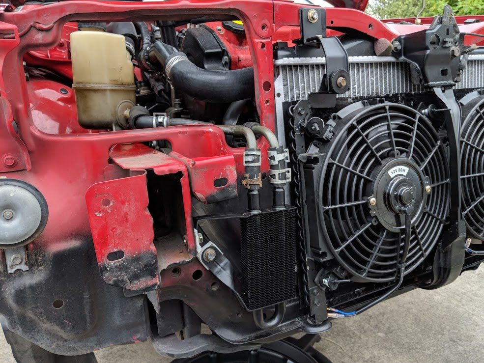
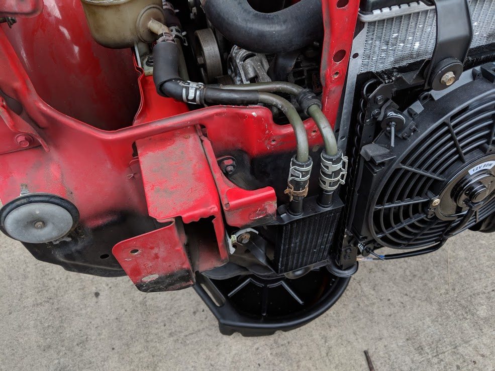
The V6 is obviously a bit larger and will interfere with the radiator. The stock
323 radiator mounts behind the front rad support/hood latch and has a electric fan
pulling from behind. From what I have read, the headers will end up just touching
the rad fins. I need to find a different radiator then.
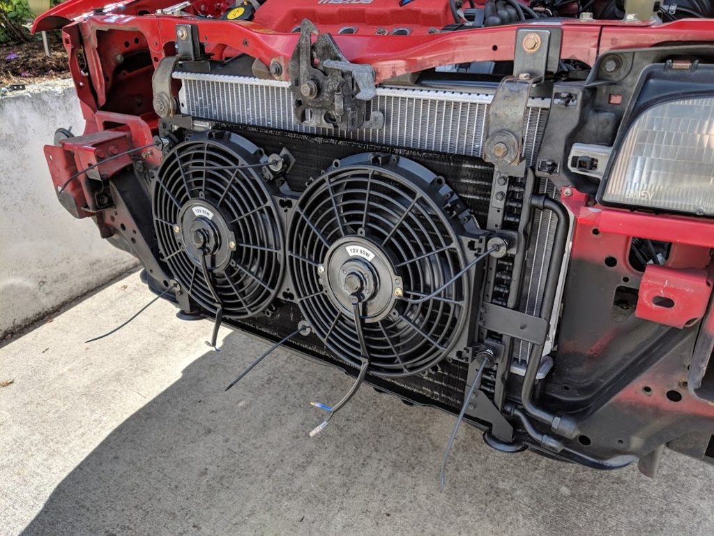
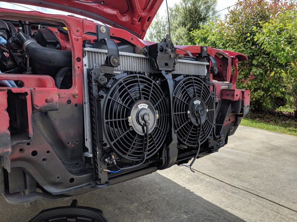
It was rumored that a Dodge Neon rad will fit nicely between the front supports.
I bought one from the junkyard and figured I would see how it works. It does barely
slide down between the headlight supports, but it doesn't clear on the top as it
is too high. I was thinking maybe if I made a removable top rad support, I could
slide it down from above and then bolt the top support back in.
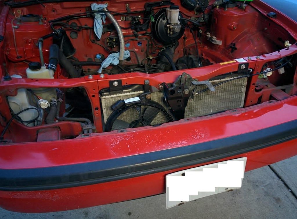
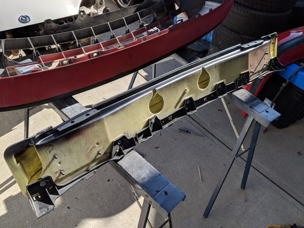
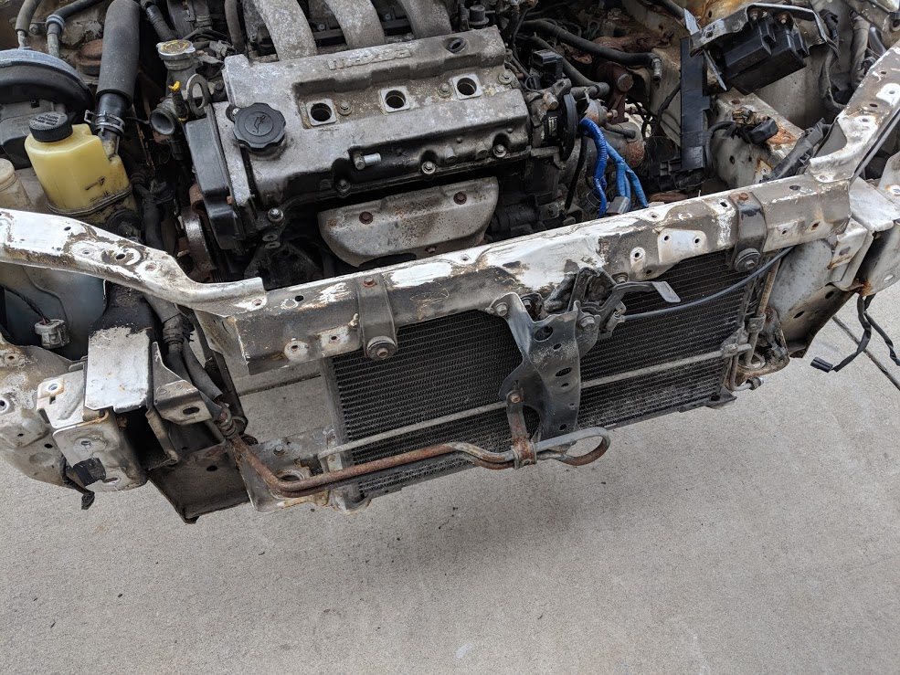
Here it is before I started messing with it:
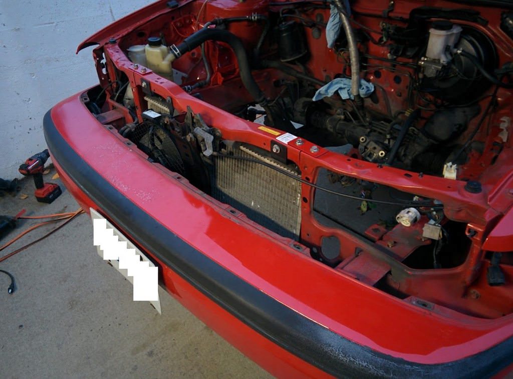
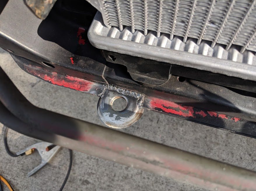
Time to break out the sawsall:
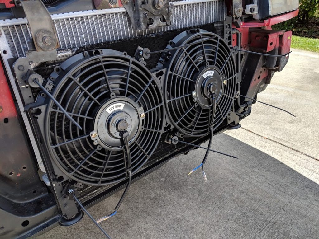
I then drilled holes to push the rubber lower mounts from the Dodge in the lower
support.
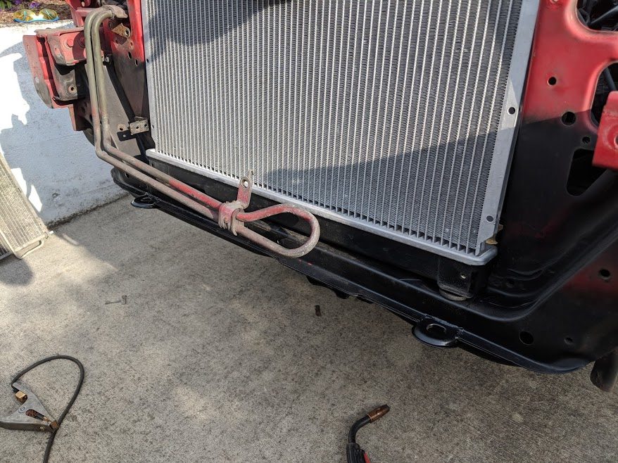
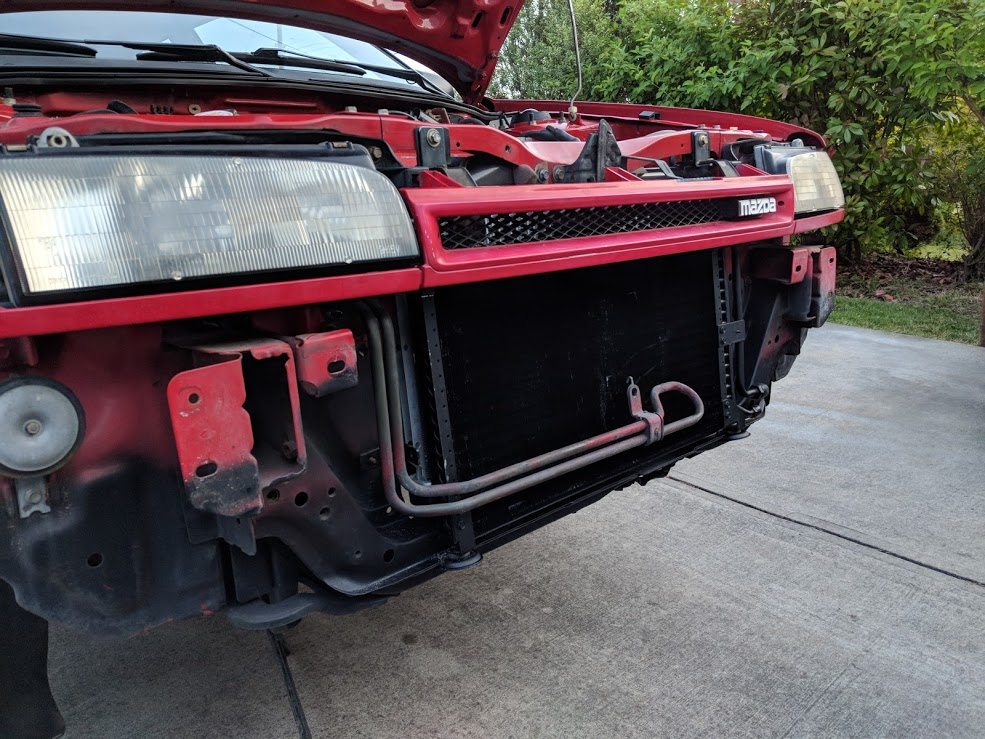
And it fit. I was very happy how well it slid in. I was also able to bend the upper
dodge mounts and use them in some stock rivnut holes.
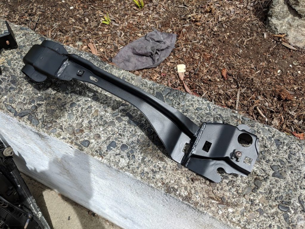
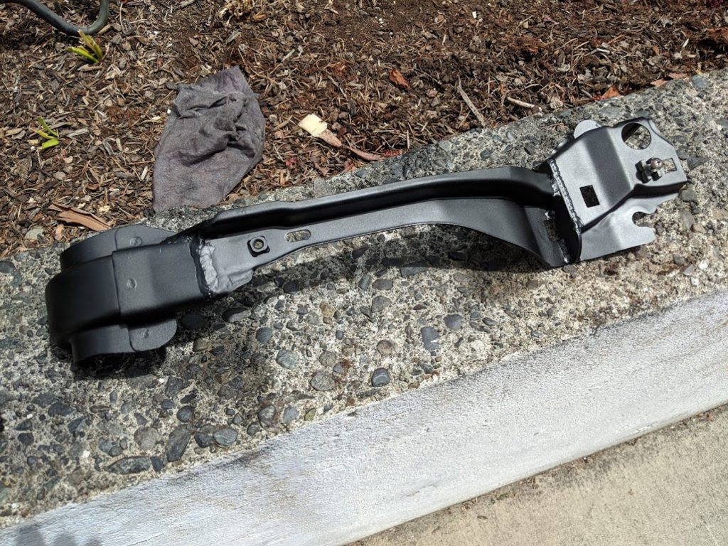
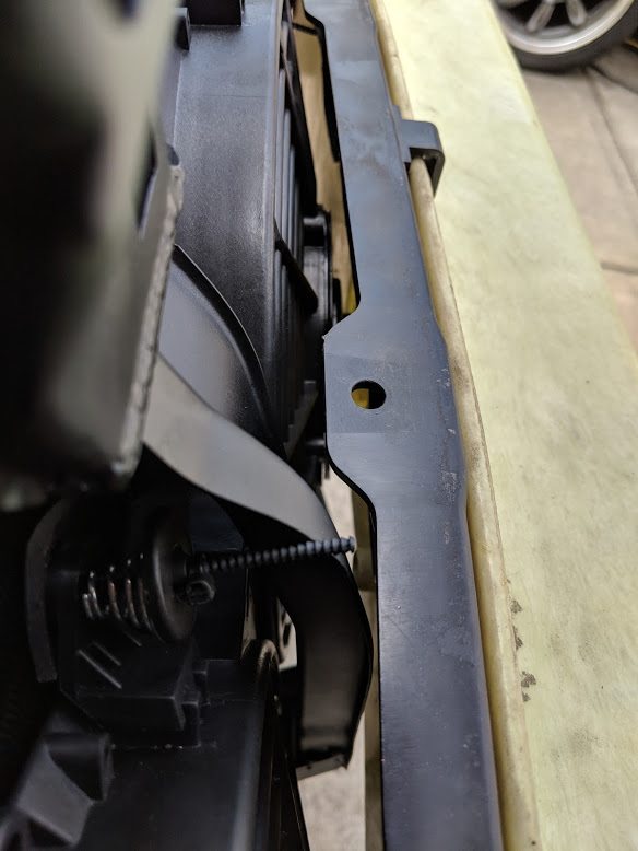
I made some plates to bolt the top support back on. I used rivnuts and some spare
Mazda bolts, so it matches. Painted them red.
The top radiator bracket, minus rubber (it was on the rad at the time). I cut off
the wings and pressed the double bend out to just a 90. It literally lined up to
Mazda holes.
I now have to deal with the fact I have no overflow fitting on either the engine
or the radiator. I found an inline rad cap assembly from a Toyota Yaris which might
work well. It uses a small style rad cap, and the Toyota one is 16PSI. It looks
like a Mazda MPV also uses the small style and is the correct 13PSI though.
I mounted an old Toyota Corolla or something AC fan. It was designed to push air
from the front, was all metal and had nice rubber isolators. Making the mounts for
this were a bit of a pain, lots of bending and tapping of holes, but it worked out
quite well.
I am quite happy how everything fit together.
So, where did I leave off with the engine? Let's jump back a few months.
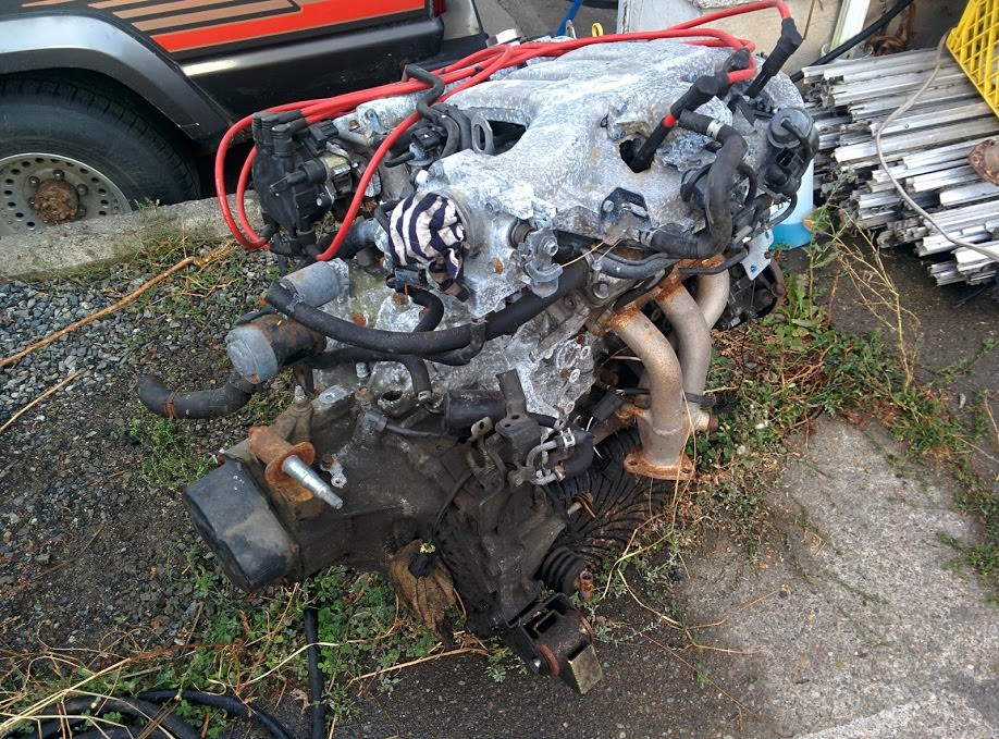
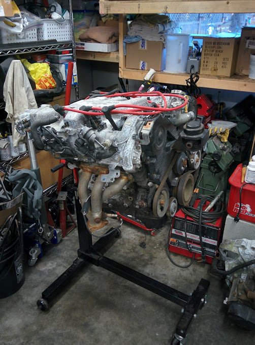
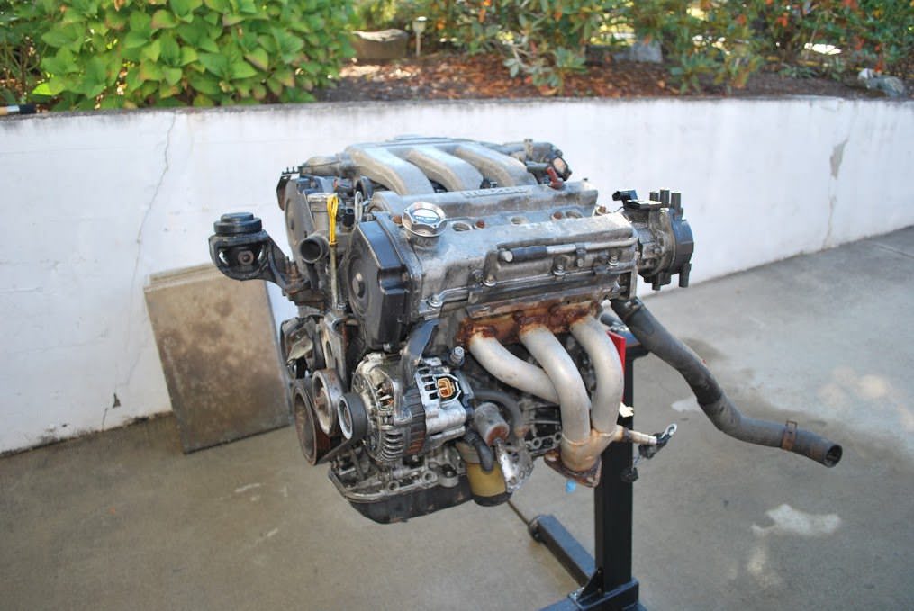
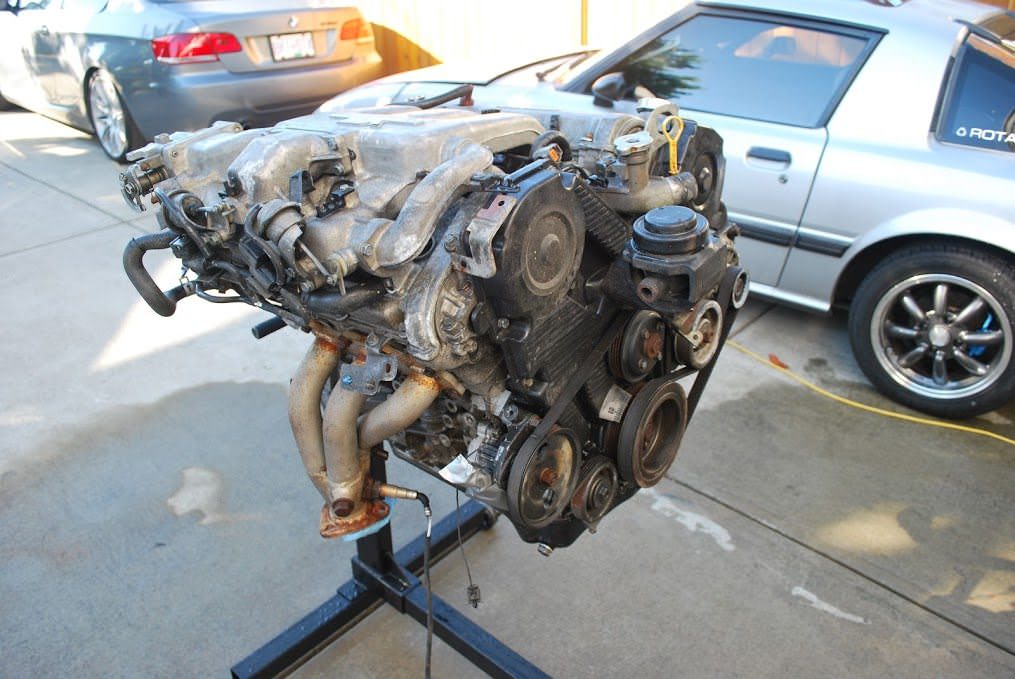
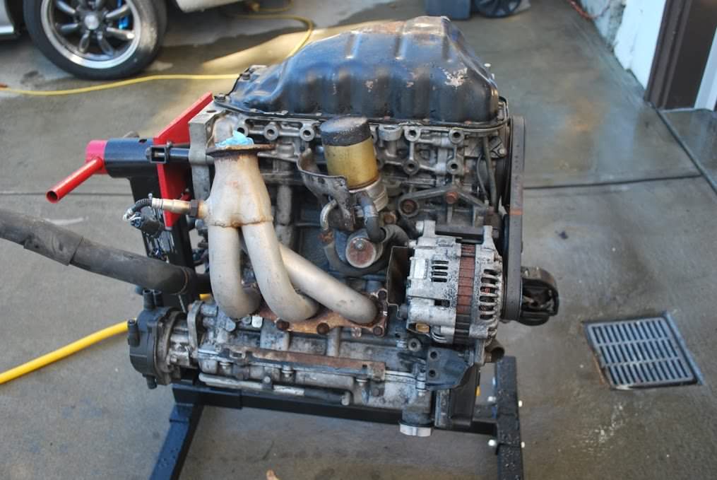
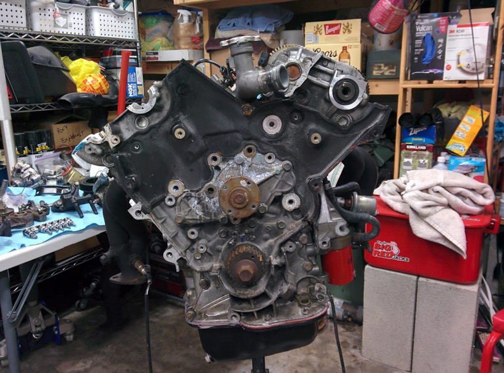
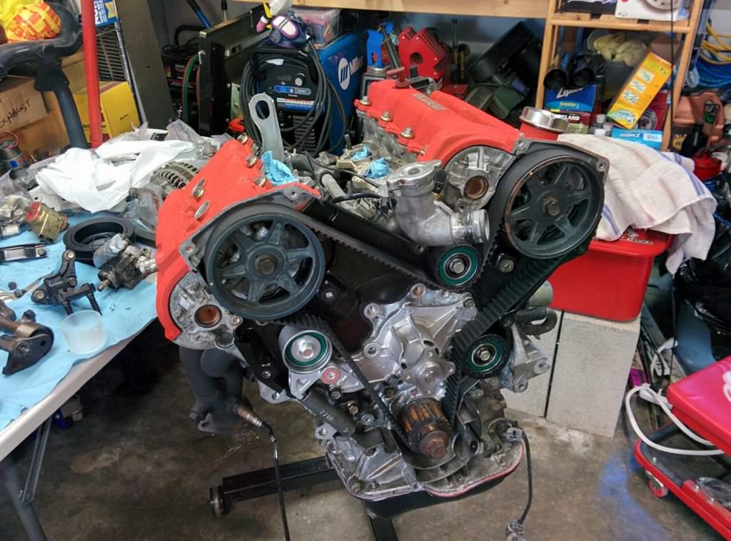
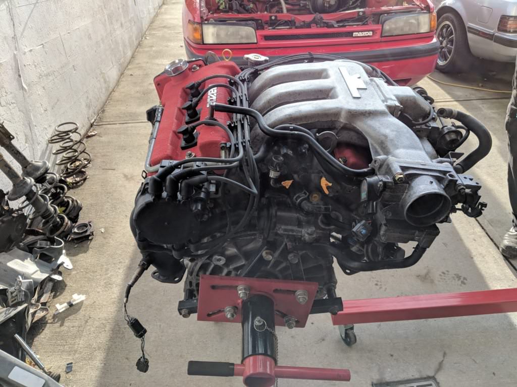
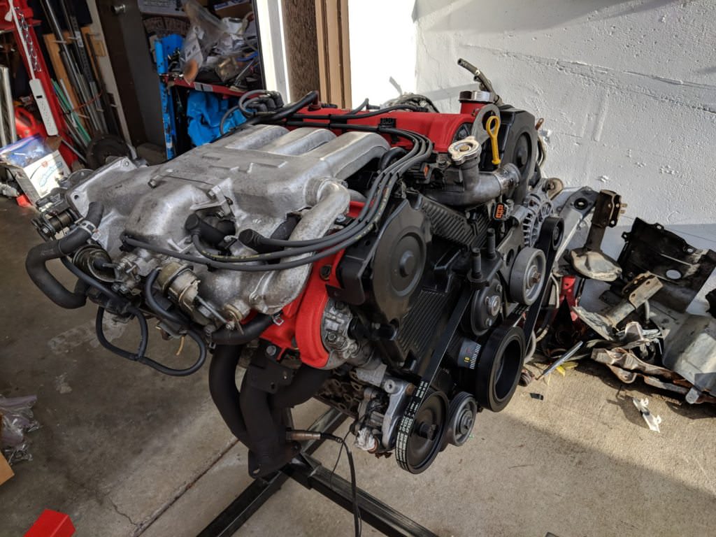
Crusty, greasy corroded KLZE up on the stand:
Broken spark plug wires, rust and corrosion on everything. It looks pretty rough.
I did a compression test. All six cylinders were around 220 PSI. That's basically
the theoretical maximum of the engine, which is 225 PSI. I was told that the engine
only had about 5000 KM on it after it was imported from Japan. Must have been pretty
low mileage in Japan as well.
Given the good numbers, I figured I would just do soft seals and clean it up. I
don't want to remove the heads.
Out comes the engine degreaser:
That is looking a bit better. Certainly a lot less greasy.
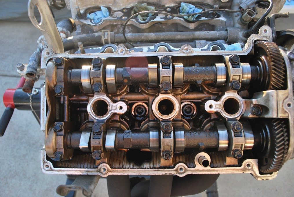
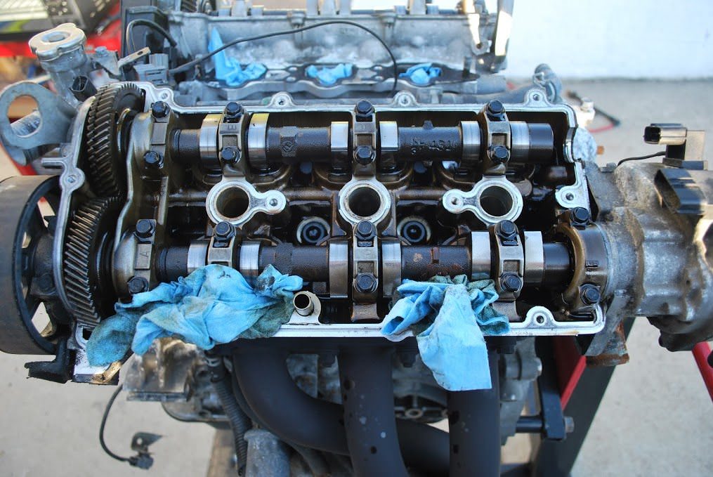
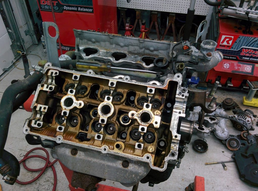
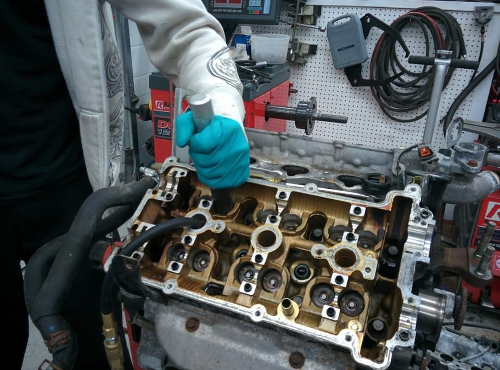
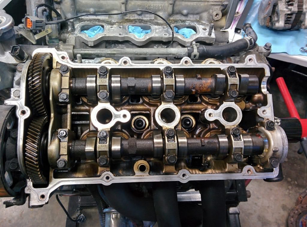
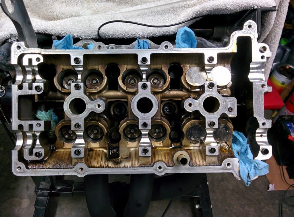
Time to take off the valve covers and see what is inside.
Clean. No sludge or discolouration. Also no scoring or wear on any of the lobes.
Confirmed that the heads and the cams both have the KL31 casting number, indicating
a KLZE. The intake valve springs are also the larger diameter KLZE springs. More
on this later.
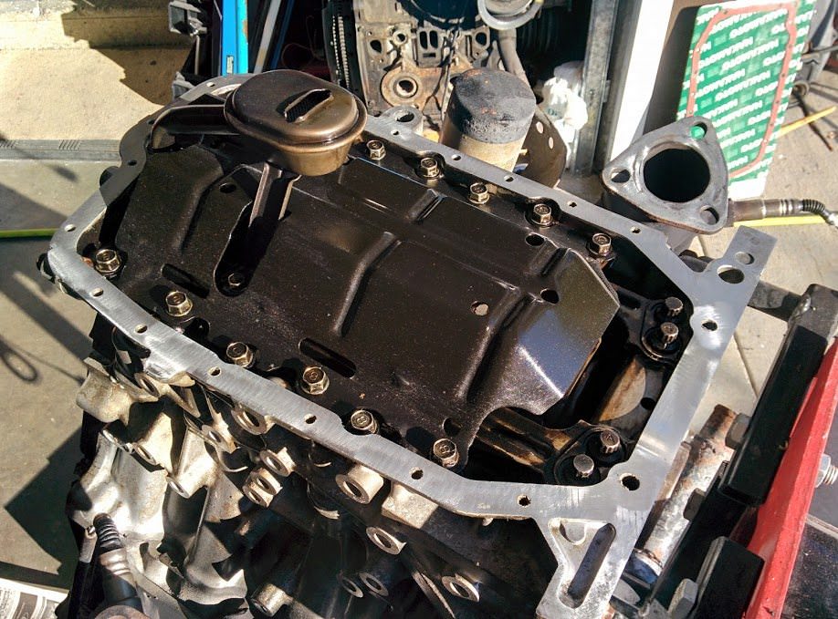
Flip it over, take off the pan:
Interesting, a factory baffle plate.
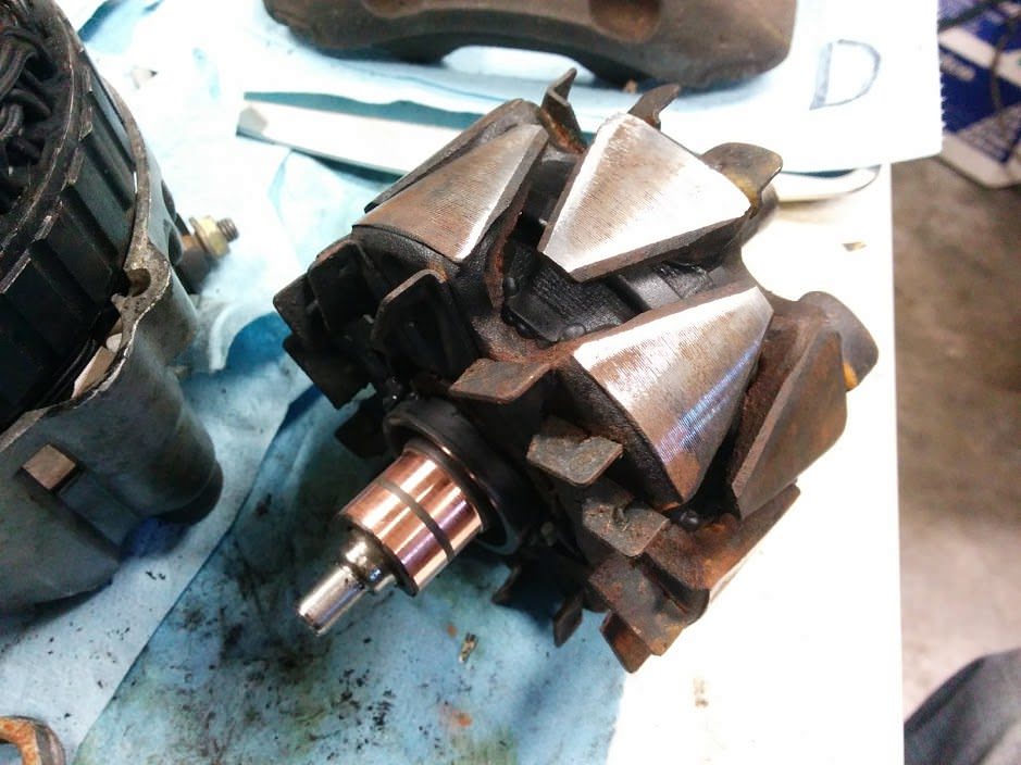
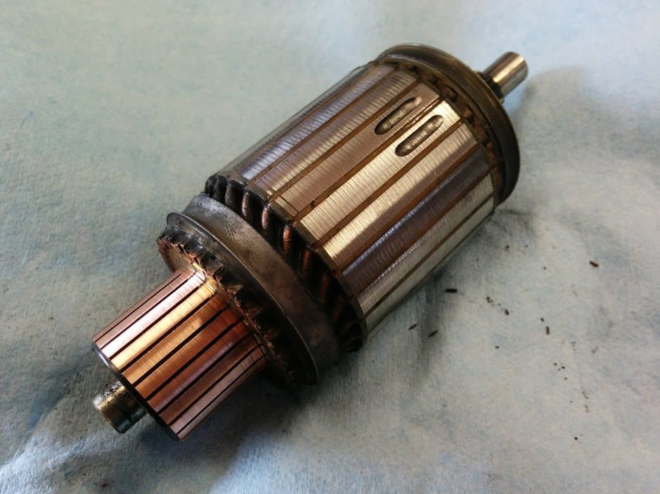
Decided to start rebuilding the alternator and starter today. Took out the armatures
and noticed some deep brush grooves in the alternator. Chucked them up in the lathe
and turned them down smooth again. I'll take a needle file and clean between the
commutator bars.
Brushes and bearings all look serviceable. Just corrosion and dried grease.
Parts have been arriving!
I think at this point, I have about 14 or 15 rock auto boxes from this project.
They shorted me on magnets a few times, which made me very cross.
Oddly enough the wholesaler closeout parts from the Florida warehouse arrived in
1990's boxes, crushed and moldy.
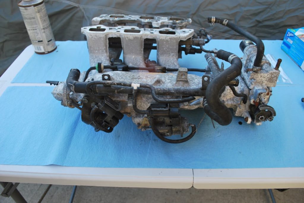
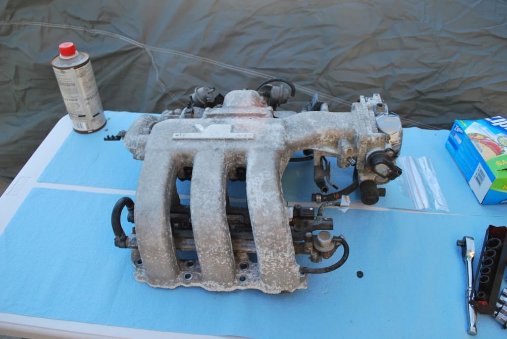
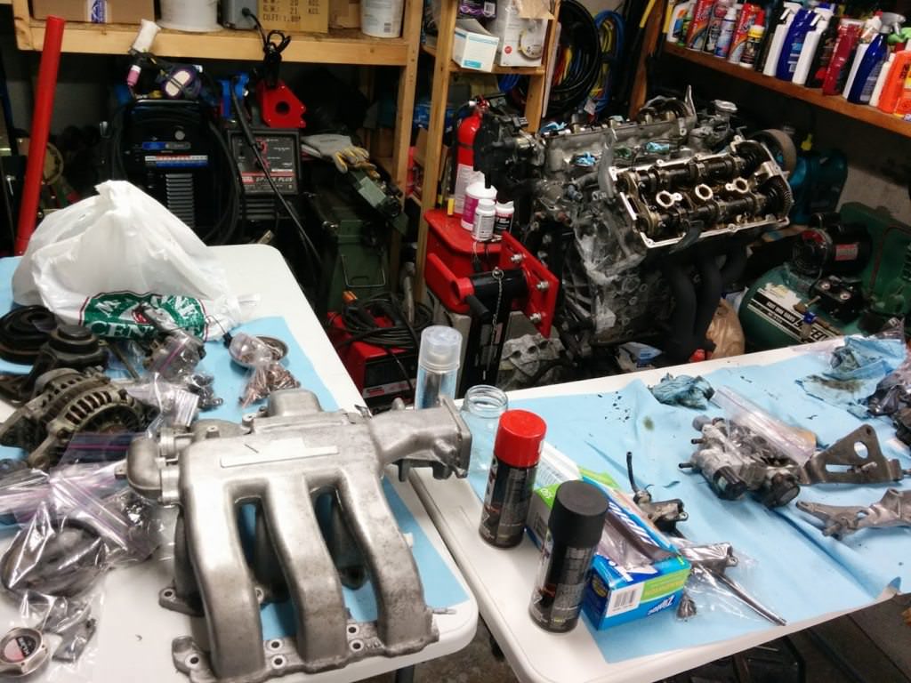
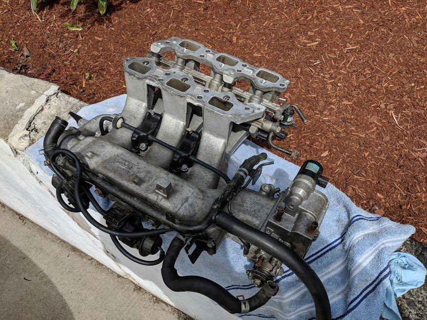
In the meantime, I've been proceeding with tearing down the accessories and dealing
with all that corrosion. I don't have a ton of pictures, but I have a few.
The aluminum on the intake was especially bad.
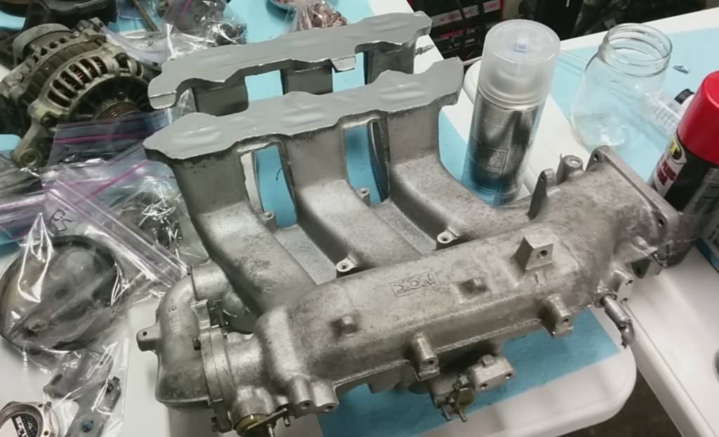
Into the glass bead cabinet it goes. After a couple hours, I had most of the corrosion
off. Unfortunately, there was still staining on the aluminum which wasn't coming
off with glass bead. I decided it was better than it was and sprayed it with a clear,
high heat semigloss.
It will do.
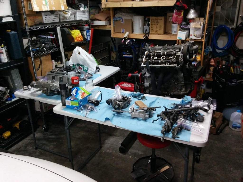
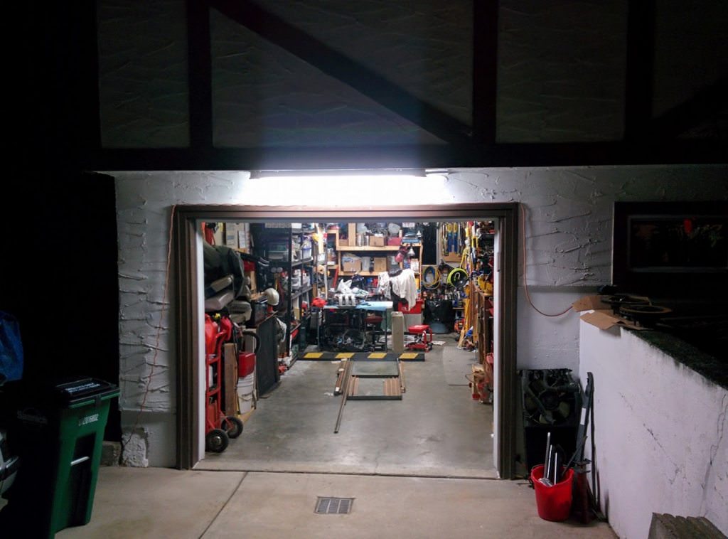
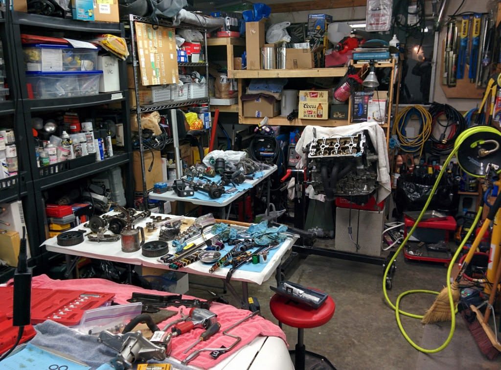
Everything laid out in the garage:
So, we left off with the intake manifold getting a good cleaning and clearcoat.
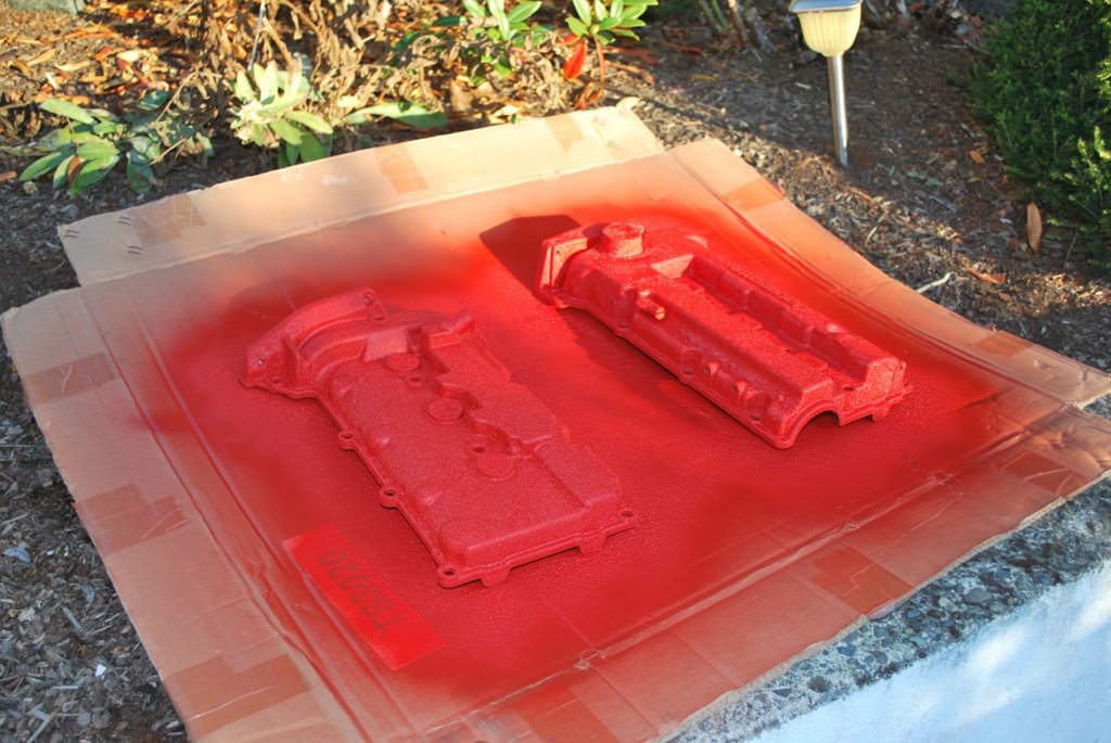
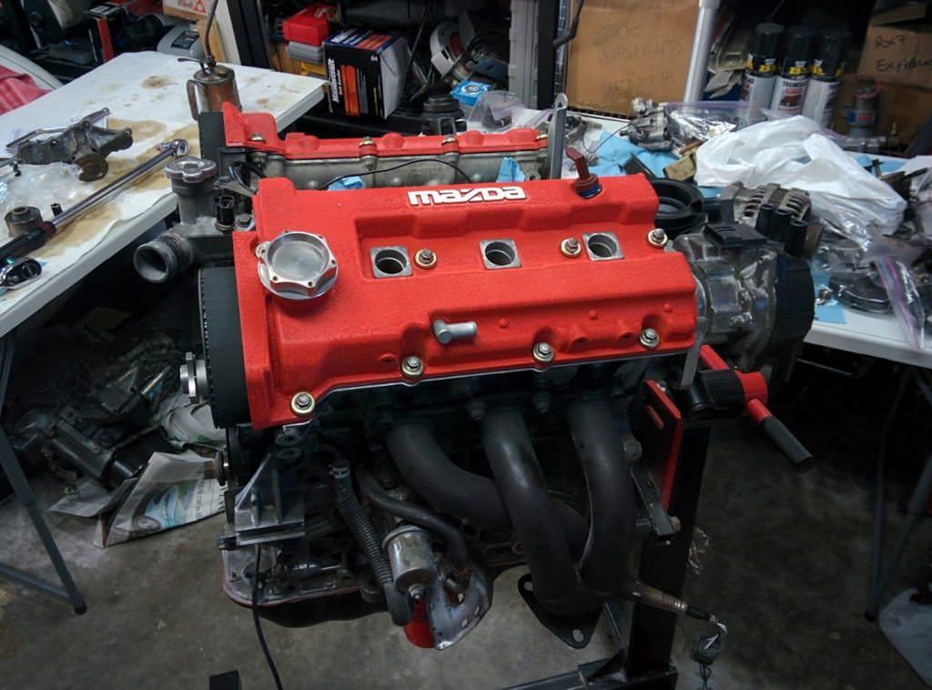
I turned my attention to the valve covers. They, like everything else were horribly
corroded. I've always wanted to have wrinkly red valve covers, so I picked up a
can of VHT wrinkle engine paint.
While those dried, I pressure washed all the schmoo off the trans. It also got a
coat of high temp clear.
Around this time, summer was coming to an end, and I was running out of light. I
bought an outdoor fluorescent fixture and installed it. Made a huge difference.
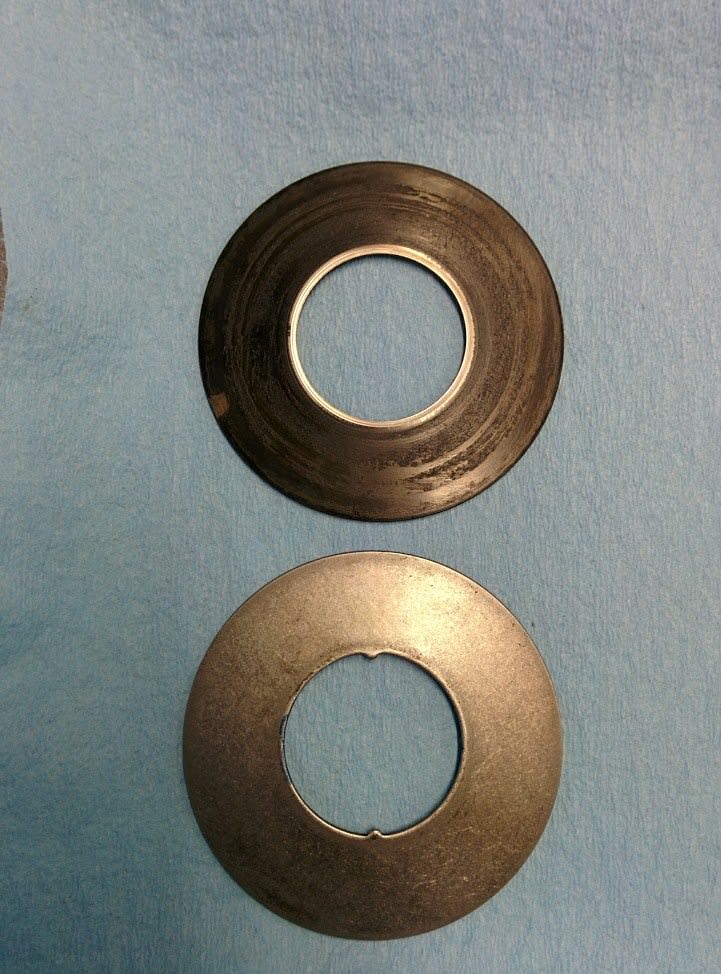
I had been doing some reading and learned that the KL engines have a few weaknesses
in their heads. First, they are known for HLA noise from dirty, sticky adjusters.
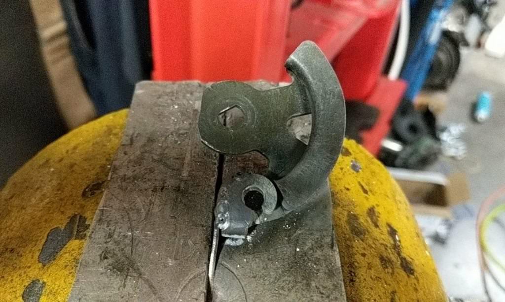
Second, they have a friction washer, which adds preload on the split gear on the
non-belt driven camshaft to take up backlash. I guess over time, this washer wears
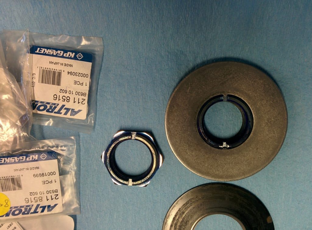
and starts to spin, making a horrible noise. Mazda corrected this in later engines
by adding two tabs which fit into slots in the retaining nut.
The third issue is specific to KLZE engines only. The KL31 head has larger intake
valves than the other K series engines. Unfortunately, they had a manufacturing
flaw, which creates a weakness and the valve retainers will crack. No one wants
to drop a valve. The solution is to swap the smaller diameter springs and retainers
from another K series. The smaller springs are also stronger. Most people say to
use a KLDE engine, but the parts fiche shows the same parts were also used in the
K8. Given that I had a junk K8, it was time to scavenge.
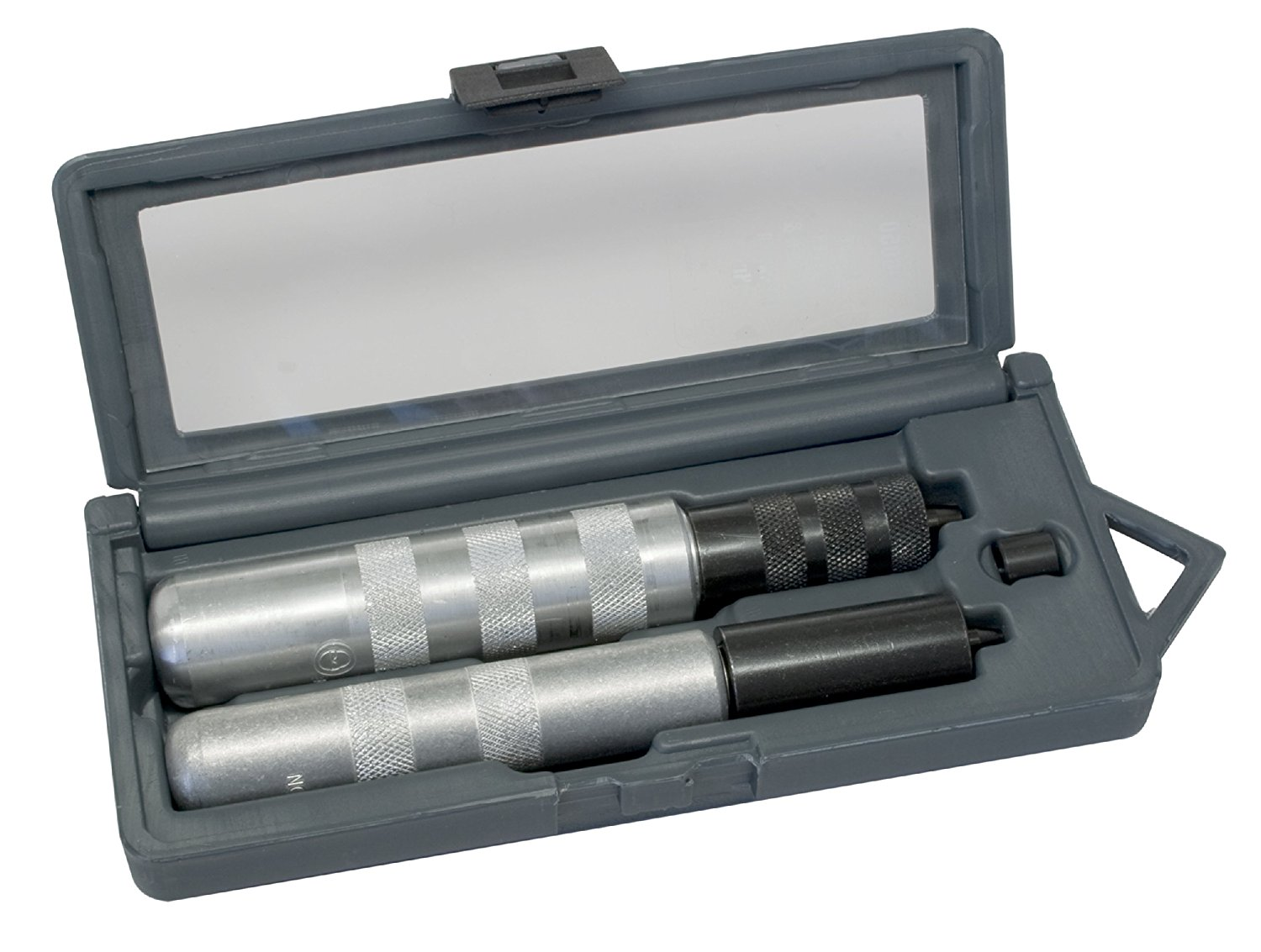
This is one of the more interesting tools I've found recently. Lisle makes this
valve keeper remover and installer tool. Basically you place it over the valve,
put compressed air into the cylinder and tap the tool with a hammer. The keepers
will suck themselves into the tool via a magnet. To reinstall, there is another
attachment, which puts the keepers back. Very handy.
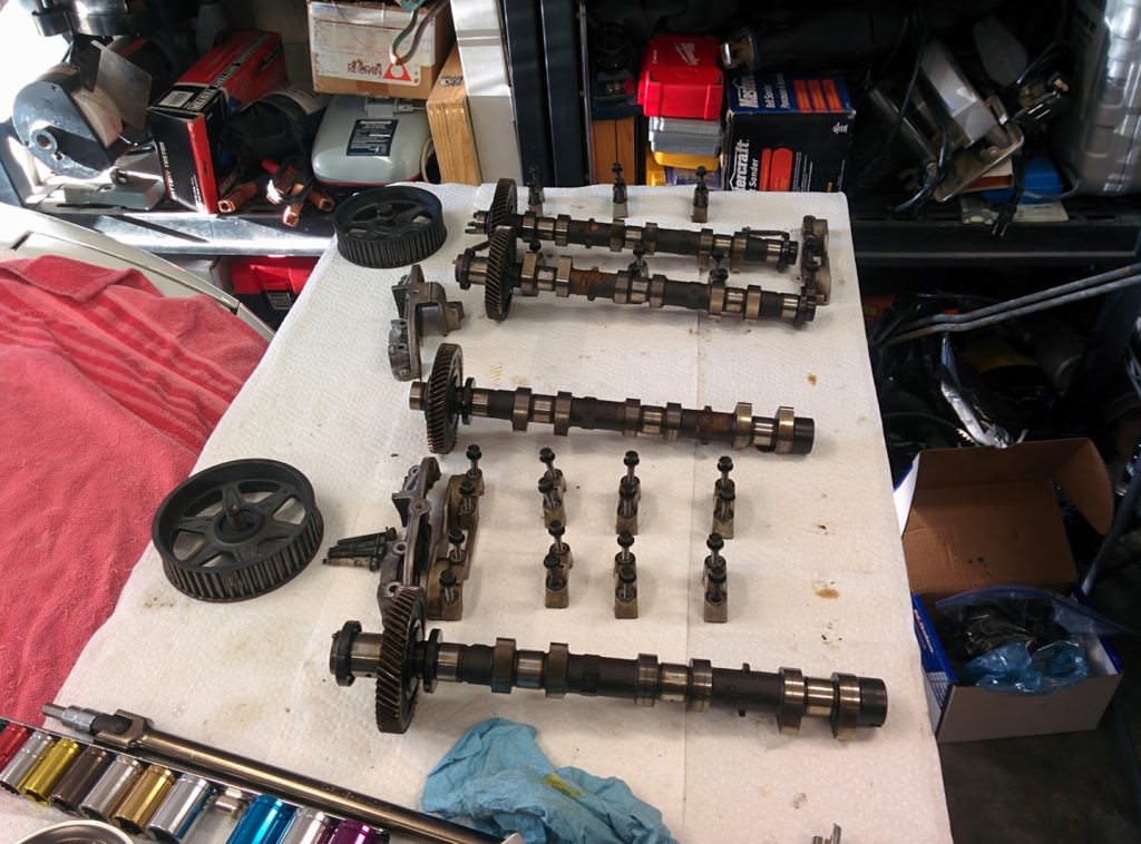
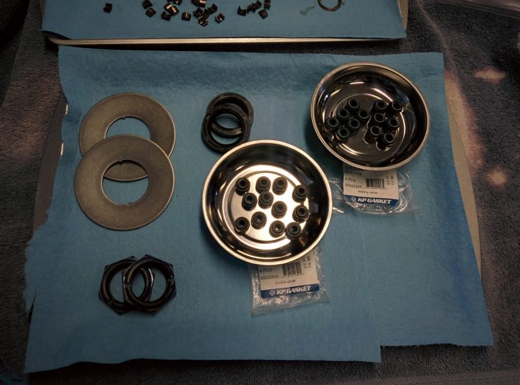
Here are all the K8 valve springs and retainers:
KLZE KL31 head:
Cams out:
New valve stem seals:
And a giant mess:
New springs in:
HLA disassembled. To do this, I put compressed air in the small oil charge hole.
This caused the HLA to explode apart along with all the gross schmoo. Clean them
in parts cleaner, put a light drop of motor oil on them and reassemble.
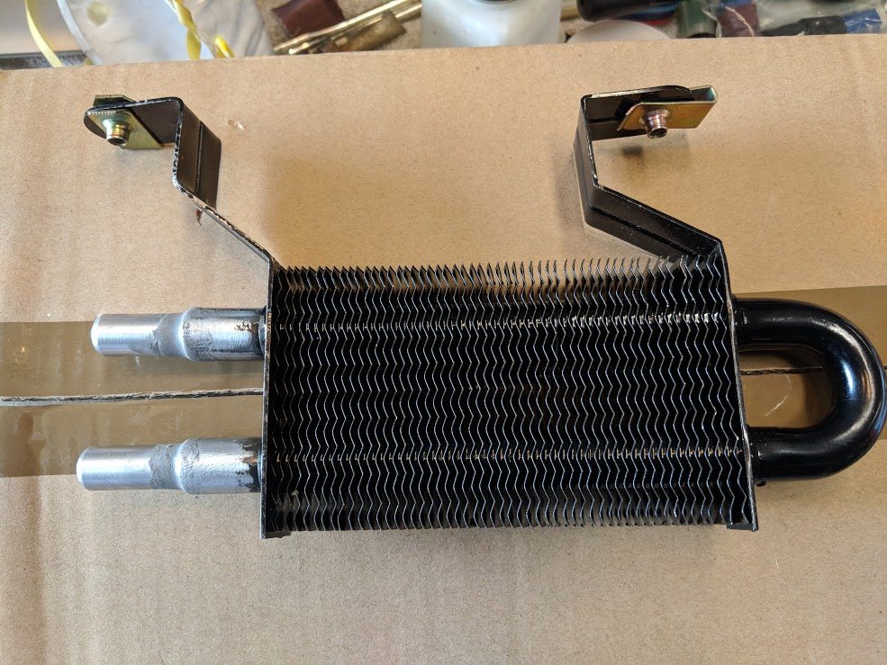
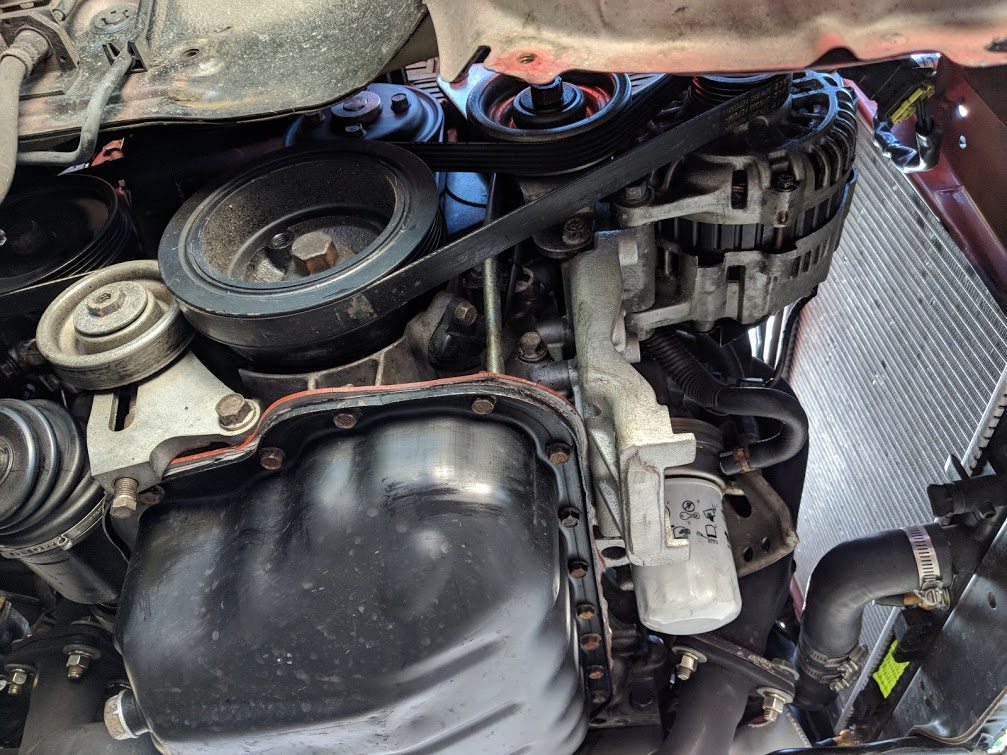
So, with the cams back in, it was time to address the water pump.
It was looking a little grim.
Some erosion of the jacket from cavitation. Not too bad. Not really much that can
be done about this.
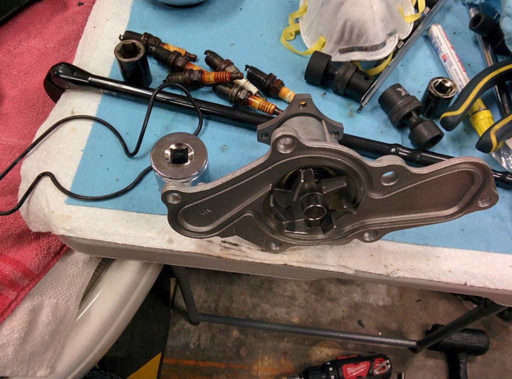
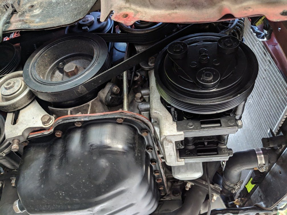
Fancy new waterpump. There are two types for this engine, one is $10, the other
is $50. This one needed the $50 pump of course.
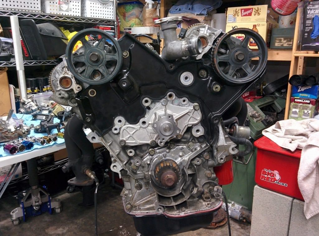
Waterpump and cam gears installed.
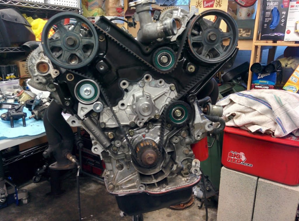
New timing belt on. Interestingly, I noticed when I was disassembling the engine
that the belt was one tooth off. I wonder how well that ran...
Now, onto the valve covers.
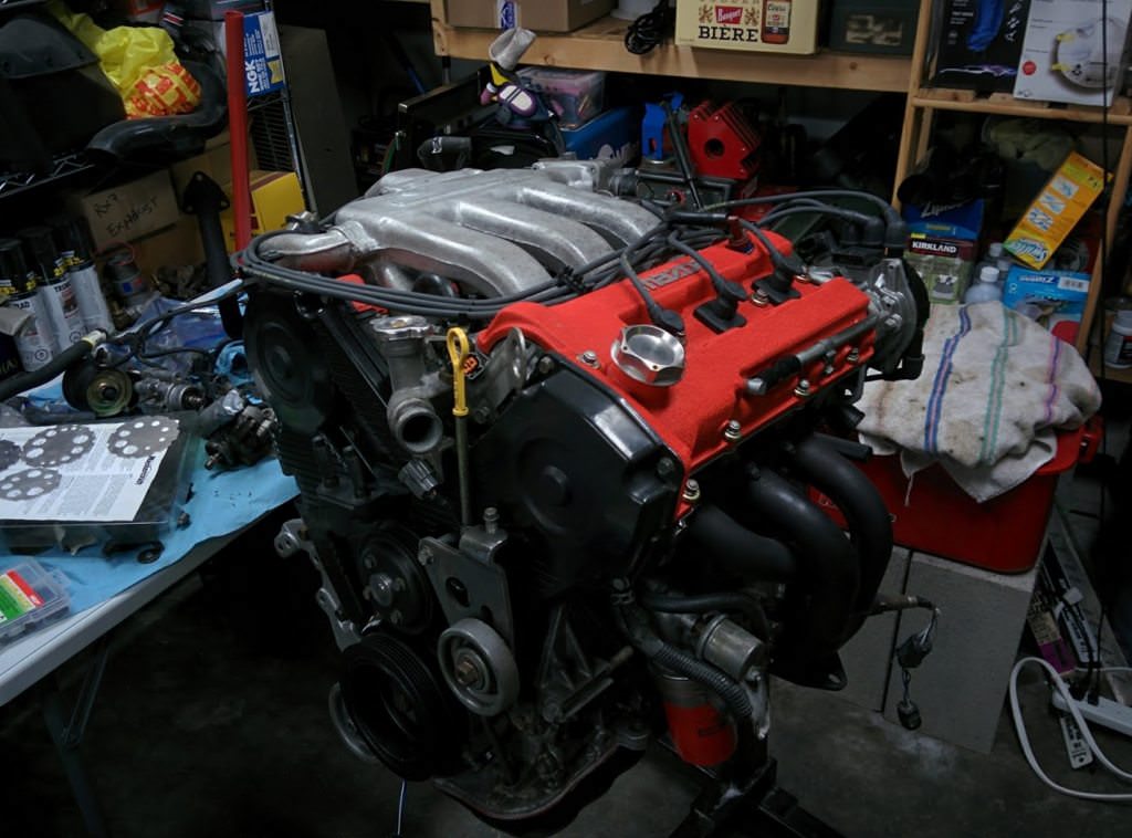
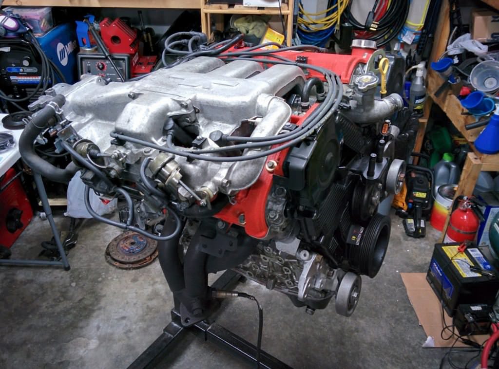
I think the valve covers turned out quite well. Some more plastic and accessories.
All ready to be mated to the transmission.
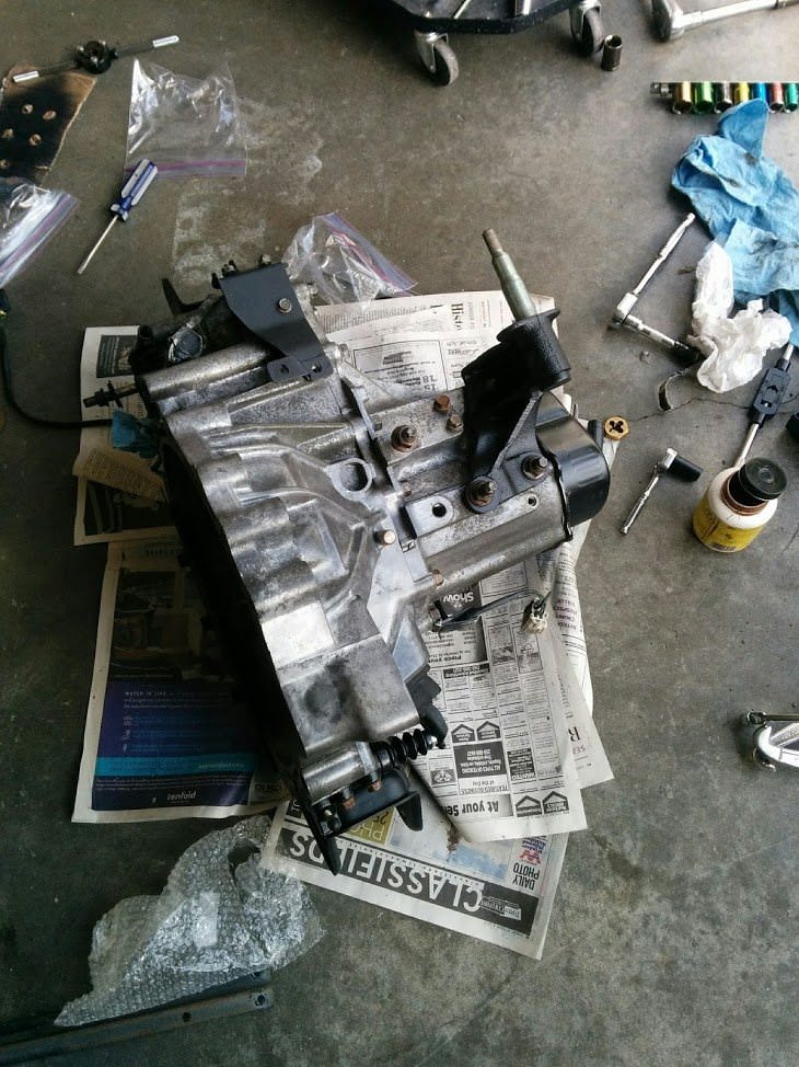
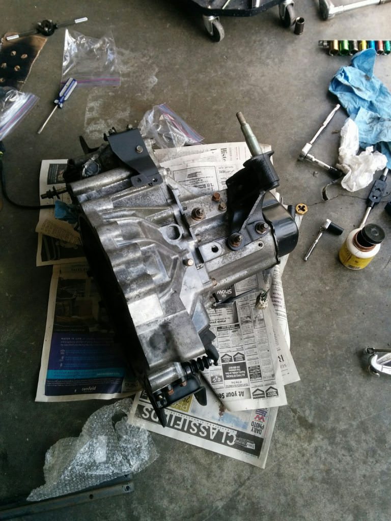
Now that the engine was sorted, it was time to move onto the transmission.
First, a good pressure washing to get the grease off. Next some wire brush work
and a bit of soda blasting left me with this.
Not too bad. A little more cleanup and some high temp clear will be in order.
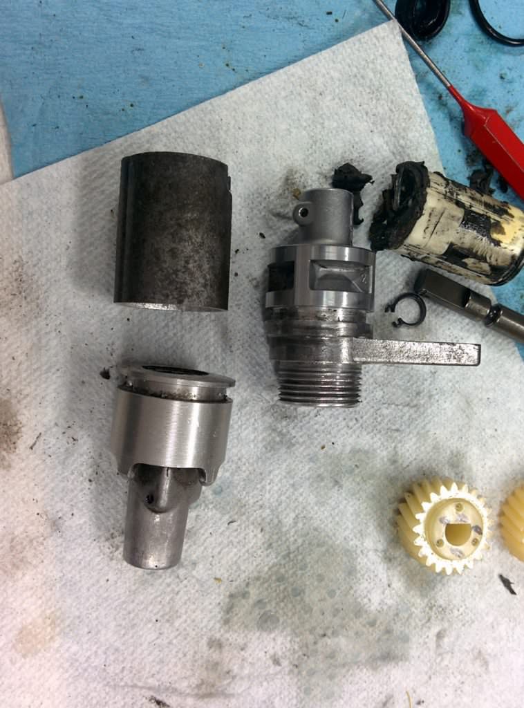
There is a problem using the K8 transmission. The MX-3 used a electronic speed sensor,
on the transmission. The automatic from the 323 was a standard cable driven unit,
with an electronic sensor in the gauge cluster itself. Now, a lot of people just
squish the MX-3 cluster into the 323 dash, or go an aftermarket route. I wanted
to retain the stock 323 gauges, so this meant I would need to come up with an adapter.
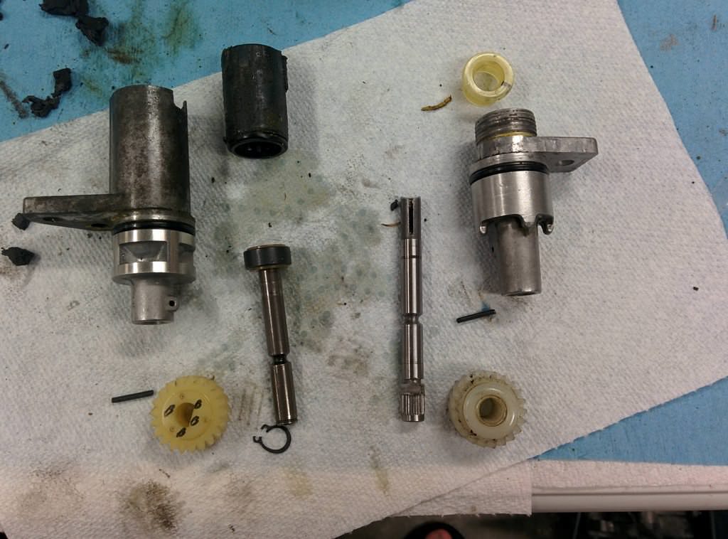
Comparing the two sensors, it was clear that while the tooth counts were nearly
identical (one tooth different) the mounting and alignment was not anywhere close.
I had seen posts of guys who just bolted the other sensor into the hole, but then
ended up eventually chewing up the gears. The cable driven style has the mounting
outer diameter concentric around the driven shaft. The MX-3 electronic one is off
axis. It is also significantly shorter.
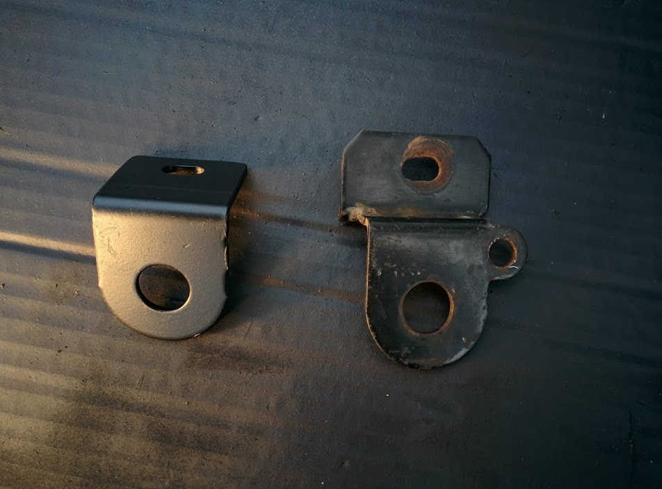
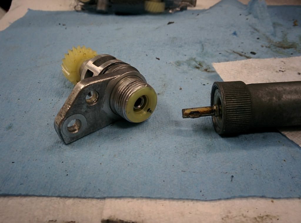
MX-3 electronic on the left, 323 cable on the right.
I needed to combine the upper cable interface from the 323 with the lower mounting
tabs from the MX3. I would also have to convert the inner shaft to accept the cable
style.
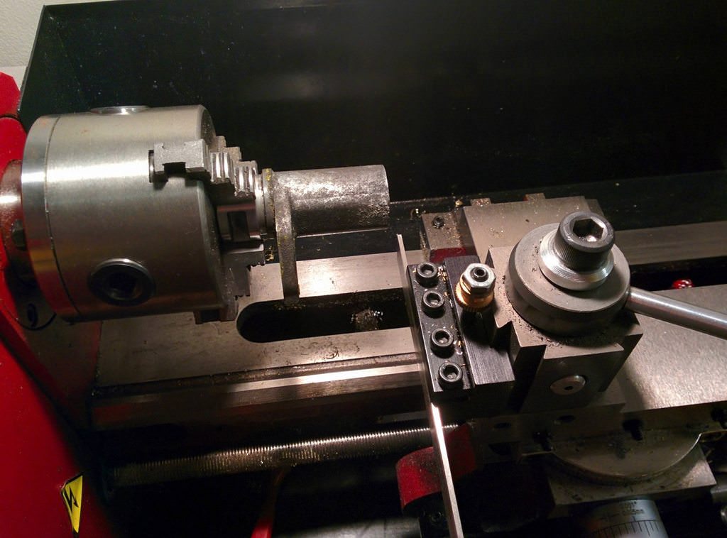
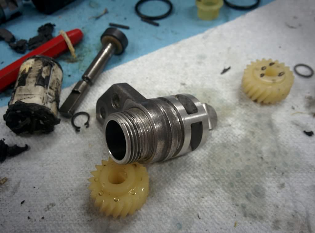
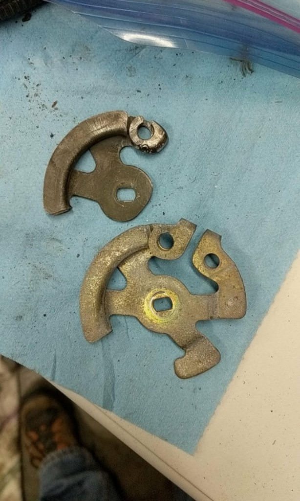
I decided to chuck the MX-3 body up into the lathe and part off the top portion.
I then cut off the upper portion of the 323 sensor, where the cable attaches. I
turned down the outside and matched it to the offset bore of the MX3 lower.
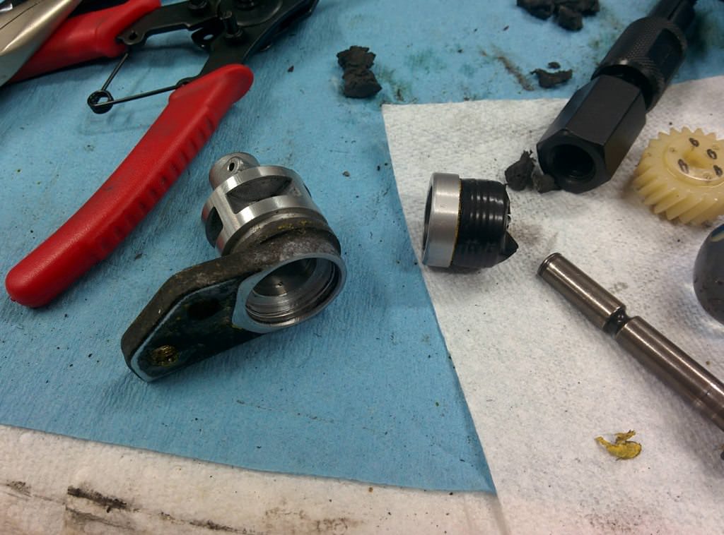
I then pressed them together carefully. Cast aluminum shatters easy! I actually
ended up ruining one of my MX-3 sensors as I did not notice a step in the inner
bore of the body.
Left side is the top of the MX-3 and the bottom of the 323 sensors that I cut off.
Right side is the two other halfs pressed together.
There is the body all finished.
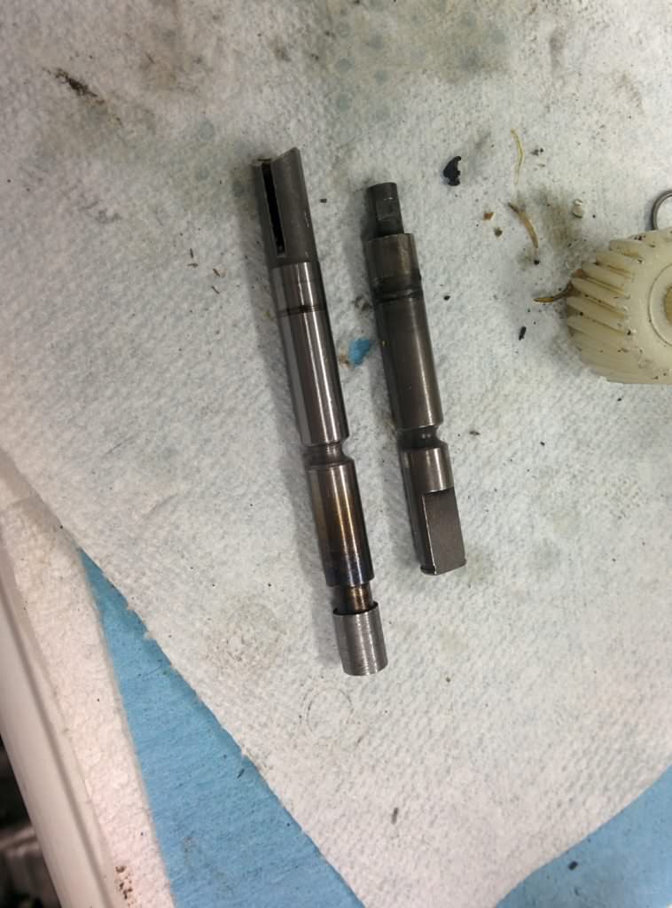
Now I had to turn my attention onto the shafts. Comparing the two, I noticed I could
cut the 323 cable shaft down to the same dimensions of the MX3 shaft, provided I
remove a small stepped bit of the drive gear, which didn't even have teeth.
323 cable style on left, MX-3 electronic on right.
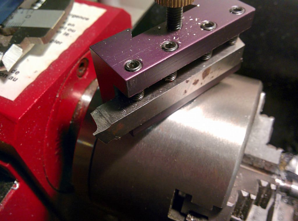
I cut off the extra and ground a tool to cut the tiny C-Clip groove. It was my first
time grinding a HSS blank and it worked really well.
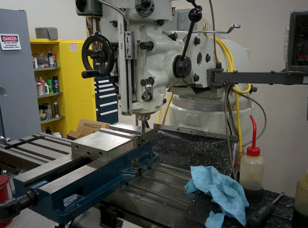
I now needed to replicate the flat spot to accept the MX-3 gear. I don't have a
mill, but a friend does.
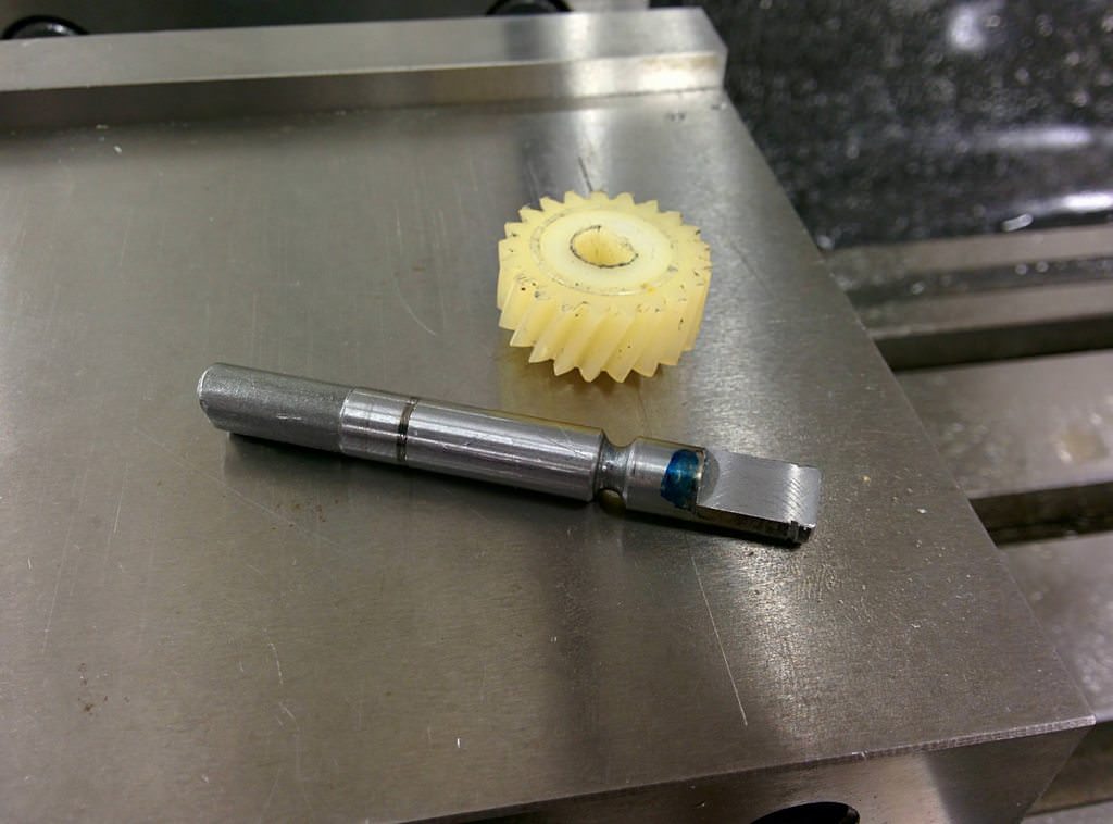
The finished shaft and turned down gear:
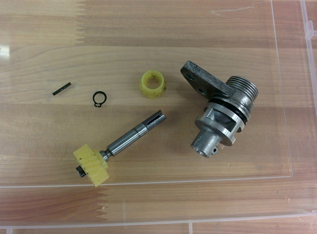
All the components:
Now it was just a matter of reassembly:
There we go. A cable driven speed sensor for a K8 manual transmission.
Since I was converting the car from automatic to manual, it was time to tackle the
clutch hydraulics.
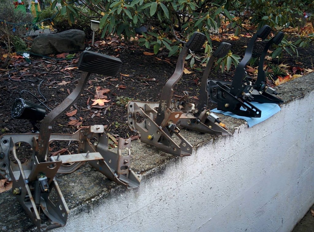
Removed the automatic pedal box to swap with the clutch pedal version.
Shown is a 323 auto pedal box, a 323 manual and an MX-3 manual. I am finding Mazda
likes to make things almost the same, except for one little difference. The steering
column mount on the MX-3 is about 1/4" off from that used on the 323. Luckily I
also had a manual 323 pedalbox laying around, so I used that one.
For some reason, my 323 had no swaybars whatsoever. According to the parts diagrams,
all should of had at least a front bar. Given that I had the entire front subframe
of the the MX3, it was just easier to swap the whole thing. This got me a quicker
ratio rack, wider track width and swaybars with endlinks.
Using the MX-3 spindles meant that I also needed to use the MX-3 brakes. Just like
the pedal box, the calipers look near identical, but are slightly different, to
accommodate the 1" larger brake discs.
Since I also had the MX-3 rear subframe, I decided to bolt it in as well. This gave
me rear swaybars, some weird Mazda four wheel steering setup like what was used
in the RX-7 and disc rear brakes!
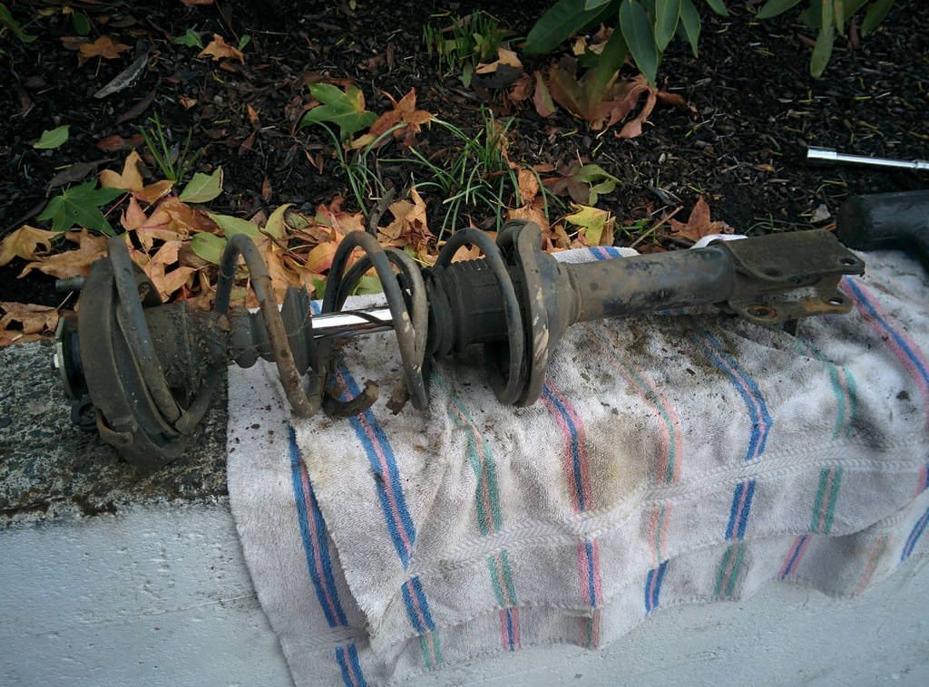
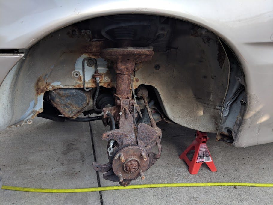
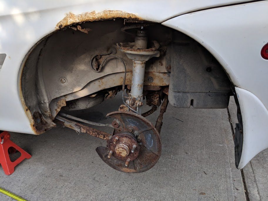
I knew the stock 323 suspension was pretty worn out, but I was not expecting what
I found on the rear:
The rear spring was completely broken. I can only imagine the dukes of hazzard style
jumps my grandmother must have taken with this car!
The struts and springs off the MX-3 were in pretty good shape, they looked to be
replaced recently. Fronts were Monroe and the rears were KYB GR2.
Now it sits, waiting for its new heart.
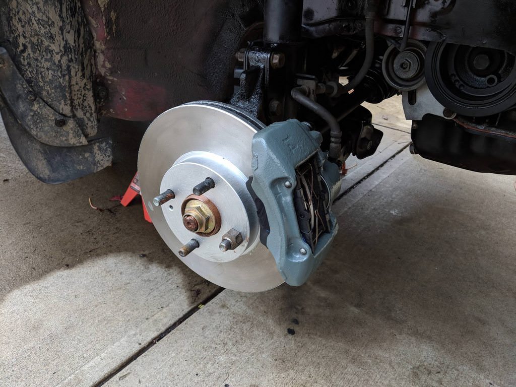
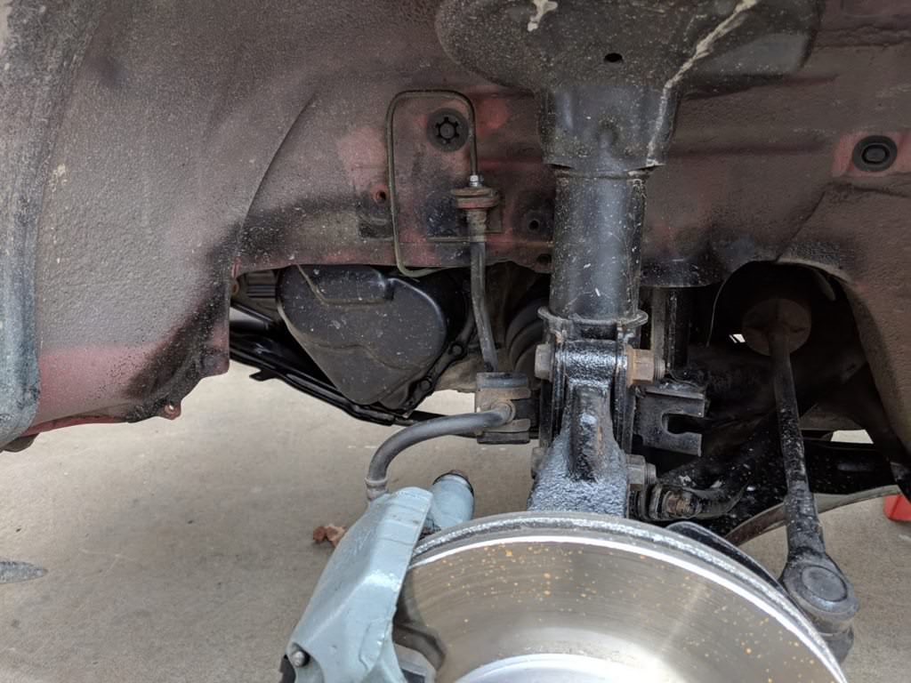
Swapping the MX-3 subframes meant that I also had MX-3 brakes. The front discs are
now larger by almost an inch, and I have disc brakes in the rear, instead of drums.
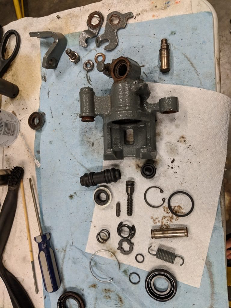
Loaded calipers were too expensive, or I was just too cheap, so I decided to rebuild
the calipers myself. The front calipers are easy, but the rears are slightly more
fiddly, due to the integration of a parking brake.
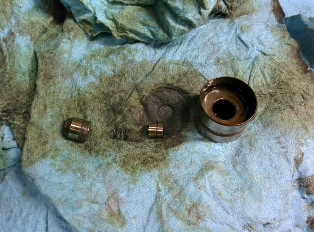
Here you can see all the bits. The first time I put them back together, the parking
brake mechanism wasn't working too well. It would apply pressure, but would max
out the lever travel quickly. It turned out there was dirt in one of the c-clip
grooves, allowing the parking brake rod to only apply a bit of pressure, then release.
It took me a bit to figure this out, as moving it by hand would move the piston
against my hand, but I couldn't press hard enough back on the piston to cause the
clip to pop out of place.
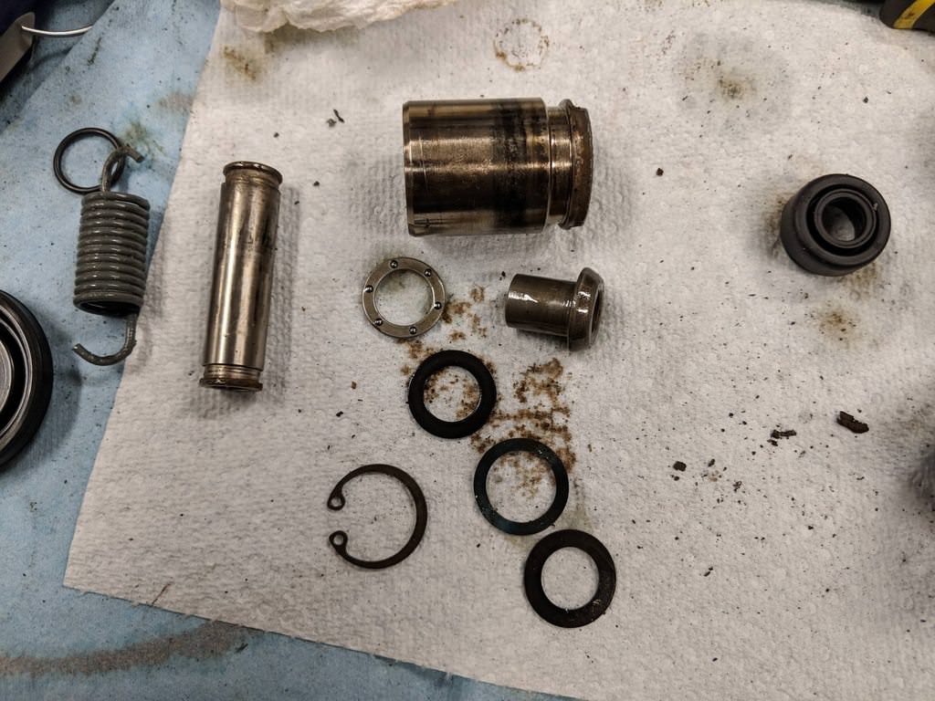
Even the little piston had a few components inside:
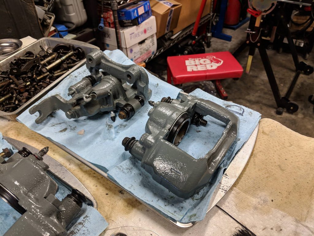
I painted them gray and slapped them back together:
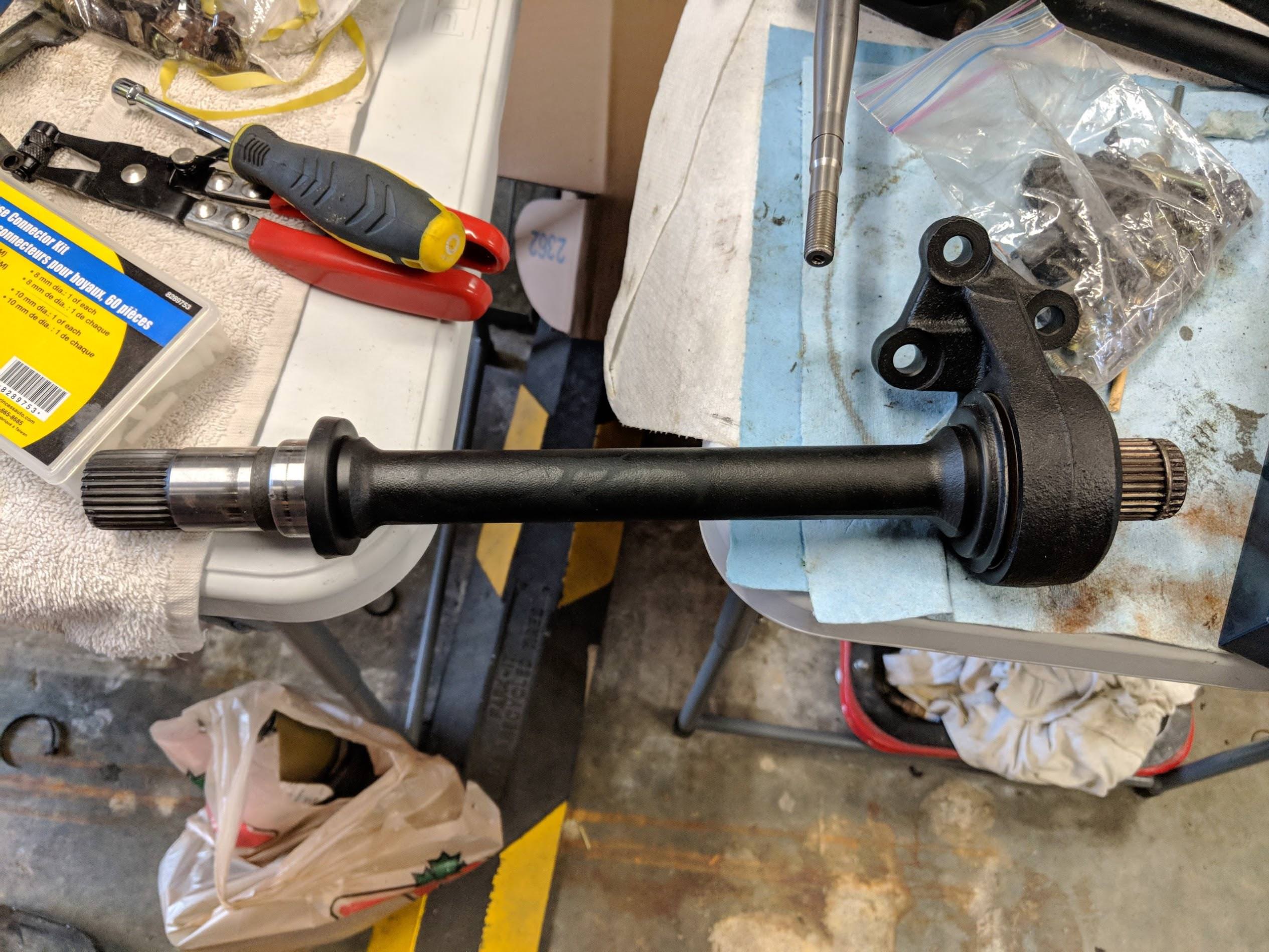
I also rebuild the intermediate shaft, using the part numbers I posted previously.
The carrier bearing was completely seized.
Here are the brakes back on the car:
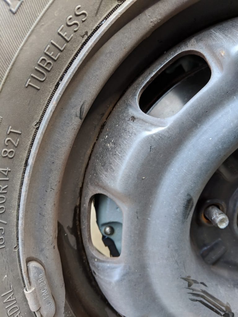
I just clear my wheels:
Hopefully this will be one of the more useful posts in this project
thread. It took me a lot of digging and translating from Russian to figure
this out.
As you know by now, Mazda used the K series engines in North America,
specifically the 1.8L K8 and the 2.5L KL-DE. Interestingly enough, they used
the same ecu wiring harness plugs for these engines as the KL-ZE used (KL36
specifically). This allows me to use an MX-3 engine harness, the 323 body
harness and any K series ECU with the KLZE engine. Also, oddly, any K series
ECU will run any K series engine. (I suspect that the injectors on the 1.8L
flow less than the 2.5L to compensate for the displacement difference.)
This means that people will swap a KL-ZE into their MX-3 and then just run
the stock K801 ecu. Apparently it runs fine, but does not have the correct
VRIS variable intake soleniod opening points, a lower RPM and will run on
the rich side. Alternatively, people will pull a KL48 or KL55, or a KL07 ecu
from a 626 or MX-6. These were the 2.5L ecus, which meant they would have
run a KL-DE, which had the same fuel injectors as the KL-ZE, but was tuned
for a different intake and VRIS, as well as a lower compression ratio and
cam profile. Better, but still not perfect.
JDM ecus are hard to find for some reason. Instead, the long dead online
forums are filled with guys selling KL-ZE SuperJDM!11!Weeaboo EPROMS, or
some version called the Probinator. (The Ford Probe also came with the KL-DE
motor, and a KL55 ecu). There are lots of suggestions to get a K801 ecu and
put in a KL31 tuned EPROM. The suggestions state you need a specific version
of the K801 ecu, one with the stock EPROM having a label containing -20XX
instead of the -16XX versions. I figured that someone must have figured out
how to tune this specific firmware version, and not the -16 version. Since
the K801 ecu I had was a -16XX, and the KL-ZE tuned K801 ecu which was
orignally in the car from the field was lost, I started looking around for
options.
Jumping forward a bit, after finding a few other ECUs (three K801 of
different firmware and a KL55 out of a probe), I actually got my hands on a
famed KL-ZE tuned K801 ecu. Curiosity won, and I dumped the EPROM file. The
file was a 1:1 match to the stock KL31.bin file from a stock KL-ZE KL31 ecu.
The message boards which played this up as such an improvement and a miracle
were wrong. All someone did was luck out that the KL31 EPROM data ran well
enough on a specific rev of the K801 ecu. It really is impressive this
worked at all, as we will learn later, because the K801 ecu only supports
one timing map and uses different table offsets in the EPROM. There are also
many reports online that this method of ecu modification does not work well
across the entire range; the engine runs pig rich at idle and leans out
randomly across the table. I suspect the only reason it works at all is the
ecu is smart enough in closed loop mode to ignore the bad tables. I
confirmed this operation as well with a wideband. Its a poor tune.
So, I continued reading and digging. I came across a Russian Mazda owners
forum, which seemed to have made significant progress in decoding the
different ECU types. Google translate saved the day and I was able to glean
some good information. The information was mixed in with a healthy helping
of mockery of decadent American pigs and their stupidity trying to just swap
entire EPROMs. I knew I was on the right track, as I had come to the same
conclusion.
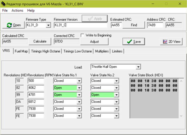
They had some good information about VRIS:
(There are three tables in the ECU for VRIS, which set the state of the two
VRIS solenoids for different RPMs, based on throttle position of slightly
open, half open or fully open.)
KF engine, KF11 ECU Europe (direct collector intake):
Throttle slightly open / half open / fully open:
0-4312 all closed
4312-6406 VRIS1 open
4812-6406 all open
6406-7500 all closed
------------------------
KL engine, KL01 ECU europe (short collector intake):
Throttle slightly open / half open:
0-7500 VRIS1 open
0-7500 VRIS2 closed
Throttle fully open:
0-3250 all closed
3250-6250 VRIS1 opened
4250-6250 all open
6250-7500 all closed
------------------------
K8 engine, K801 ECU (curved collector intake):
Throttle slightly open:
0-3875 all closed
3875-6312 VRIS1 opened
4656-6312 all open
6312-7500 all closed
Throttle half open:
0-1875 all closed
1875-2688 all open
2688-3875 all closed
3875-6312 VRIS1 opened
4656-6312 all open
6312-7500 all closed
Throttle fully open:
0-3875 all closed
3875-6312 VRIS1 opened
4656-6312 all open
6312-7500 all closed
------------------------
Throttle slightly open / half open / fully open:
0-4062 all are closed
4062-6812 VRIS1 opened
4781-6812 all open
6812-7500 all closed
------------------------
KL-ZE engine, KL62 ECU (curved neck intake)
Throttle slightly open / half open / fully open:
0-1906 all closed
1906-2594 all open
2594-3906 all closed
3906-6312 VRIS1 opened
4688-6312 all open
6312-7500 all closed
------------------------
Interesting and useful information for sure. VRIS is dependant on the intake
geometry, which makes sense. You want to select VRIS points which match
whatever intake you are running, not so much which engine.
I also learned that the true JDM intakes number their VRIS solenoids
opposite from the North American intakes. This means, if you are using a NA
wiring harness on a JDM intake, you need to swap the VRIS lines, either on
the harness, or via the ECU firmware. I have never seen this information on
any English site before.
Another thing I should probably post. Here is a list of what ECU came in
which cars.
There are a lot of different ECU numbers, but some run the same firmware
files. For example, KL48 ecus run KL55 firmware.
Now, these crafty Russians had another trick up their sleves. They had not
only figured out where the tables were in the EPROMs, but one guy had also
written a tool to edit them! I downloaded it from Russia, got put on some
watch list and opened it up.
Well shit. This was after installing the cyrillic char set. Before it was
even worse, all ??? for each character.
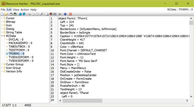
I figured I would try to see if I could fix the VB exe. After using PE
Explorer to unpack the exe (the EXE was compressed and the resouces were not
able to be edited directly) I was able to open it up with Resouce Hacker.
Awesome, now I can see the captions and text for each button. This was
decimal unicode, so #1056#1077#1076#1072#1082#1090#1086#1088 can be
converted into Редактор,
which can then be google translated into Editor. This value can now be
written back into Resource Hacker.
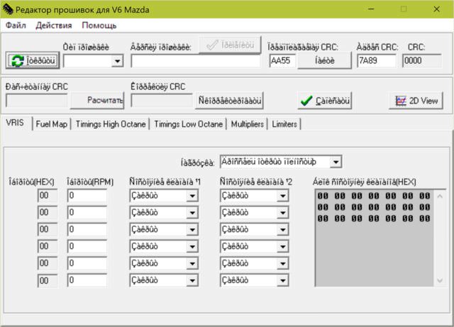
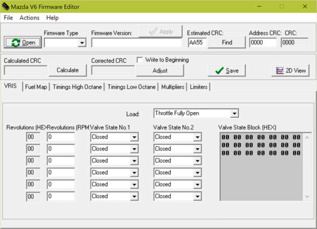
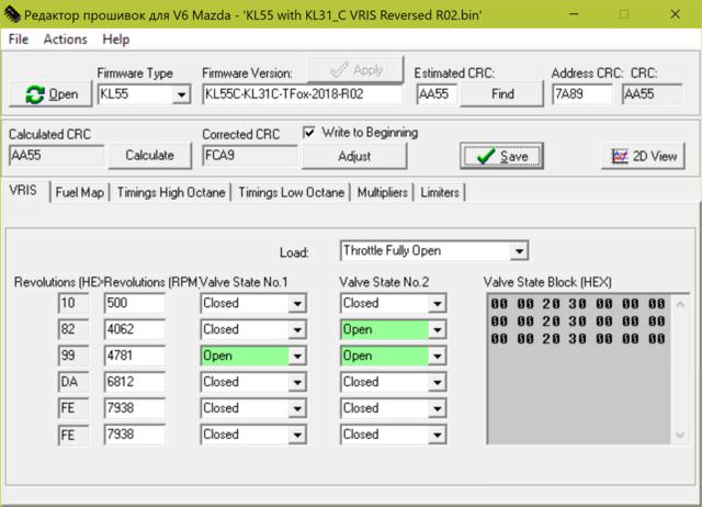
After a long and tedious process, I was left with this:
Woo, it can edit VRIS, Fuel, Timing and more!
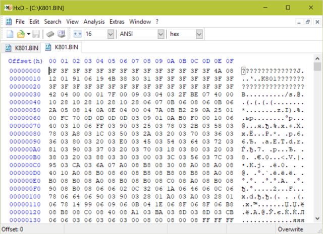
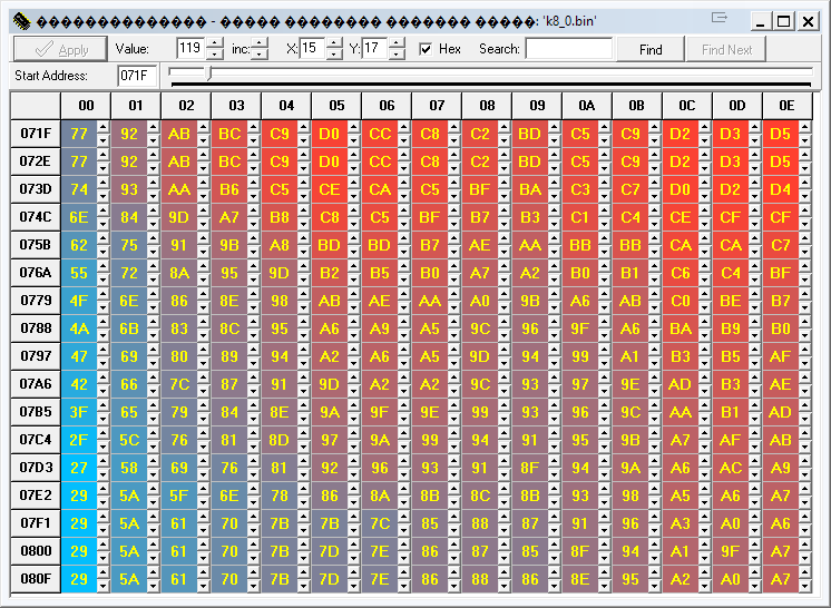
Now, how do we use this program? Let's look at one of the files floating
around the internet, K801.bin. Let's open the file in a hex editor:
All firmware files have an ascii header section. Here we can see this file
is called K801. We can load it in the firmware editor, but the editor needs
to know what offsets to use in the file. There are a few options for K801,
K801_A, K801_2 etc. We need to select the correct one. We will know we have
the correct one when the VRIS table is correct, along with the fuel tables.
After a while you can get a pretty good idea of what the tables should look
like. For a beginner, lets refer to the VRIS tables from before. A K801
should have:
K8 engine, K801 ECU (curved collector intake):
Throttle slightly open:
0-3875 all closed
3875-6312 VRIS1 opened
4656-6312 all open
6312-7500 all closed
Throttle half open:
0-1875 all closed
1875-2688 all open
2688-3875 all closed
3875-6312 VRIS1 opened
4656-6312 all open
6312-7500 all closed
Throttle fully open:
0-3875 all closed
3875-6312 VRIS1 opened
4656-6312 all open
6312-7500 all closed
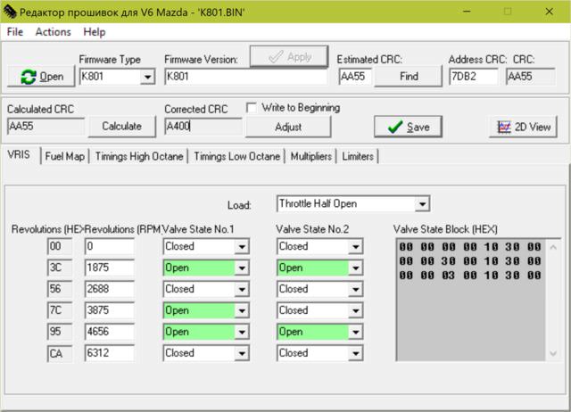
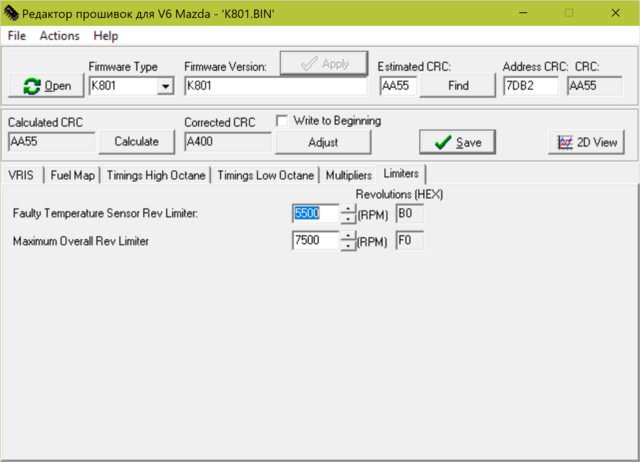
Selecting K801 in the pulldown matches this table. RPM limiters of 5500 for
faulty temp and 7500 overall also line up. Fuel and timings look correct as
well. Now that we have the offsets correct, let's dig deeper.
This tab shows the VRIS table, as well as some information about the
firmware file. We can see a calculated CRC of AA55. This is very important.
The ECU will not load any eprom files which do not have this CRC. There are
some other options, which we will discuss later.
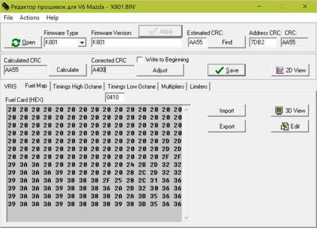
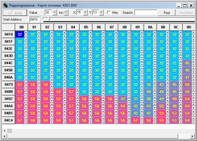
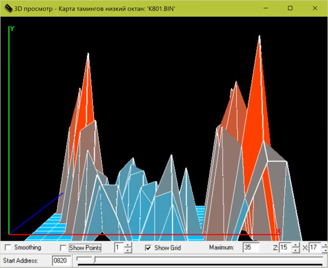
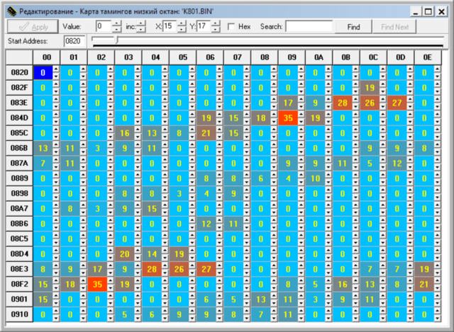
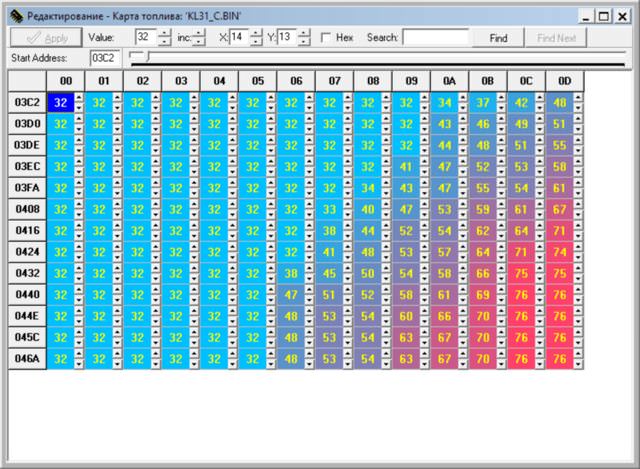
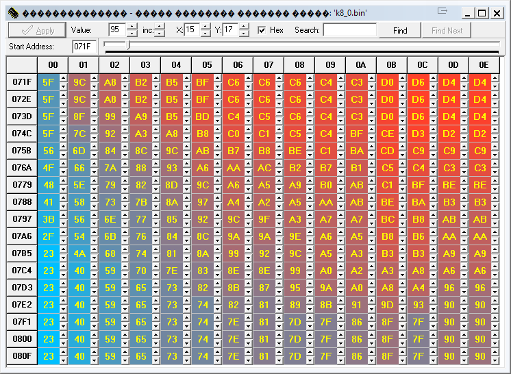
Next is the fuel map. We can import and export just the map, as long as the
overall size is the same (more on this later). We also have two handy ways
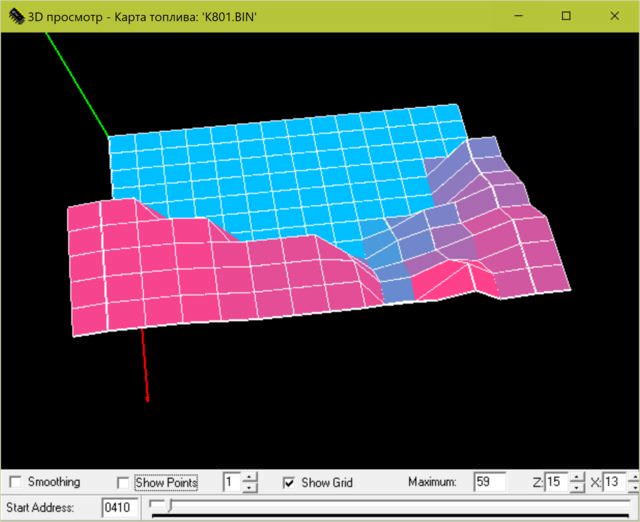
to visualize the map.
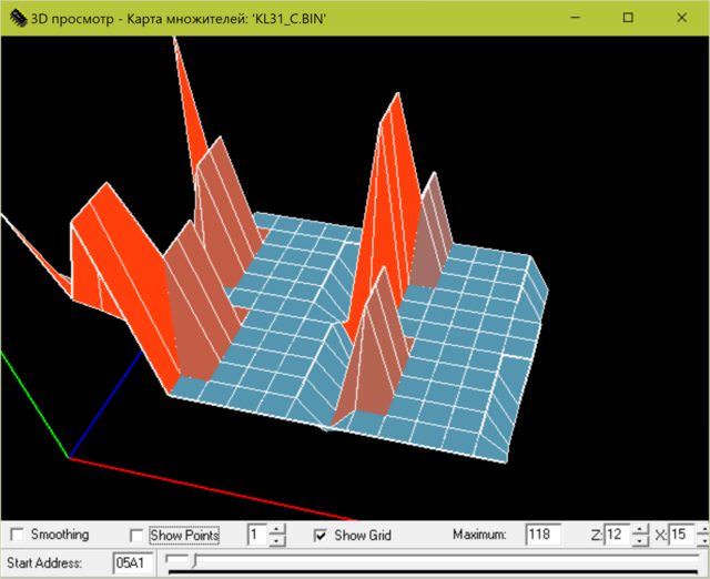
A 3D view.
A coloured table. Looking at the map, there is a progressive increase in
fuel for high load, high rpm. There also is a huge dump of fuel across the
RPM range, for higher load. Interesting, remember this for later.
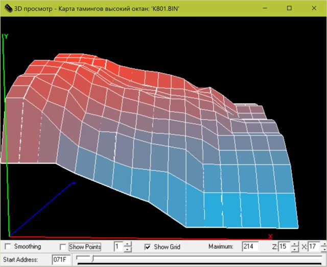
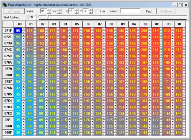
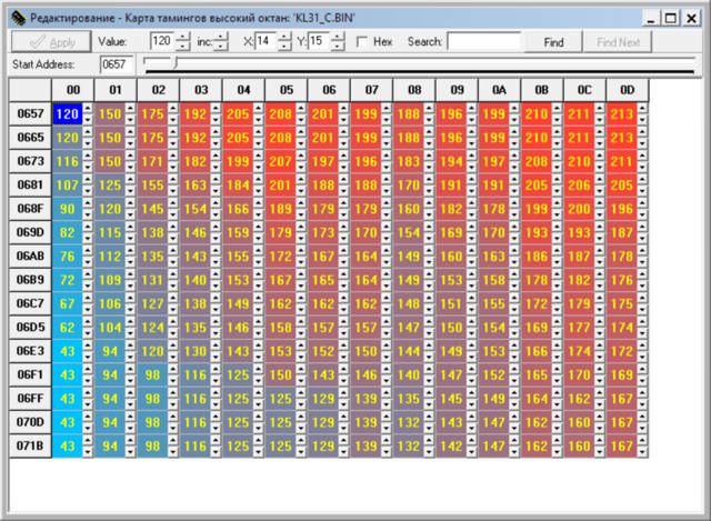
Moving on, we have a High Octane timing map:
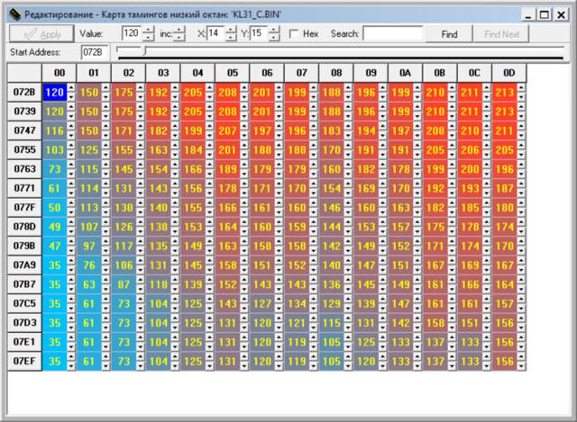
The program also supports Low Octane timing maps. I assume the ECU has a
fallback if it detects knocks.
Uh oh, that doesn't look right. Normally, I would suggest we chose the
incorrect offset values for this particular firmware file. I know though
that the K801 ECUs do not support two timing maps. This means there is only
one timing map for the 1.8L K8 engines. This was my first indication that
just replacing the EPROM in a K801 ecu with one from a KL31 ecu was not
correct.
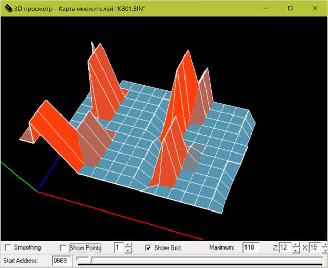
There is also a multiplier table. I am not sure how this works, or what it
does.
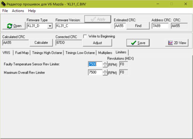
Finally, the last tab, the limiters.
So, that is the K8's ecu in a nutshell. Now, let's take a look at the JDM
KL31.
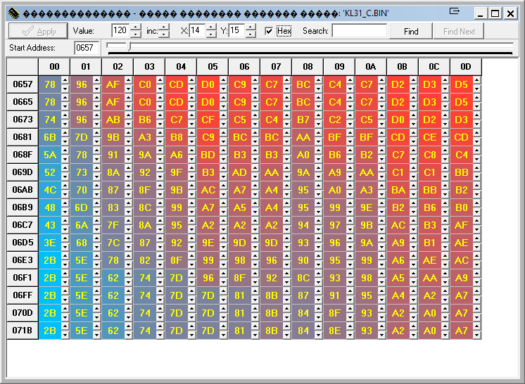
Opening up KL31_C.bin shows a header of KL31_C. This is the most popular
file online. The correct offset values are KL31_D.
Here we see the VRIS table for a long/straight neck KL-ZE intake manifold.
Also notice the CRC is AA55.
Onto the fuel map:
Very interesting. Here we see more fuel being added earlier, for the
progression to high RPM high load. What we don't see is the huge dump of
fuel across low RPMs. All the Japanese tunes omit this heavy fueling. It
seems to only be present in USDM models. Perhaps this is emmisions related?
Japanese models do not have EGR.
Also, notice the number of rows. K801 was 15x13. KL31 is 14x13. This means
you can't just import the fuel maps from each ecu. This also holds true of
the timing maps, unfortunately.
High timing map.
Low timing map.
The 2.5L ECUs all seem to support both timing maps.
Multiplier table. Again, I do not know what it does.
Limiters. Notice the JDM one doesn't care if your engine has no temp sensor.
Go ahead, ruin it. We don't need a limp mode.
So now, where does that leave us? We have a K8 ecu, which has different
sized maps for fuel and timing, not to mention only one timing map. The USDM
2.5L ECUs do support two timing maps and have the same table size for fuel
and timing as the JDM. The best results should be able to be obtained with
one of these.
I decided that my best option would be to use the 2.5L KL48 ECU from a 1994
Ford Probe GT. Let's walk through how to put the KL31 maps into it.
Something I forgot to mention earlier. There are two types of VAF or vane
air flow meters used on the K series engines. The K8 and the KL-ZE use a
JE50 VAF, whereas the rest use a KL02. Guys online are always trading and
scrambling to find the right one for each ECU. Generally the rule is you
must use the VAF type which the ECU was originally designed for. What if I
told you there was another way? There is always another way.
In each firmware, there is a scaling/calibration table which tells the ECU
what voltage scale to position to use with the VAF input.
For the JE50: A3 D7 9E D6 9A 10 95 7F 91 22 8C F5 88 F5 85 20 81 74 7D EE 7A 8D 77 4E 74
30 71 30 6E 4E 6B 87 68 DC 66 49 63 CE 61 6A 5F 1C 5C E2 5A BD 58 AA 56 A9
54 B9 52 DA 51 0A 4F 4A 4D 97 4B F3 4A 5C 48 D1 47 53 45 E0 44 79 43 1C 41
C9 40 81 3F 42 3E 0C 3C DF 3B BA 3A 9E 39 89 38 7C 37 76 36 78 35 80 34 8E
33 A3 32 BE 31 DF 31 06 30 32 2F 64 2E 9A 2D D6 2D 17 2C 5C 2B A5 2A F3 2A
45 29 9C 28 F6
KL02: F5 C3 EE 41 E7 18 E0 3F D9 B3 D3 70 CD 70 C7 B0 C2 2E BC E5 B7 D4 B2
F5 AE 48 A9 C8 A5 75 A1 4B 9D 4A 99 6E 95 B5 92 1F 8E AA 8B 53 88 1C 84 FF
81 FE 7F 16 7C 47 79 8F 76 EF 74 63 71 ED 6F 8A 6D 3A 6A FD 68 D0 66 B6 64
AA 62 AE 60 C2 5E E3 5D 12 5B 4F 59 97 57 ED 56 4E 54 BA 53 31 51 B4 50 40
4E D5 4D 75 4C 1D 4A CF 49 89 48 4B 47 16 45 E7 44 C1 43 A3 42 8A 41 78 40
6D 3F 68 3E 6A 3D 71
So what does this mean? You can search for the sequential hex values in the
firmware bin file and replace it with the other. So if you had a K801 ECU
which would have used a JE50 VAF, search for the JE50 hex and replace it
with the KL02 hex. Awesome. I have never seen this posted online anywhere
ever.
Now, remember we talked about CRC checksums earlier? After replacing the VAF
table, you will need to recompute and adjust the CRC. Luckily, the firmware
tool can do this for you. You should replace the VAF table first, manually
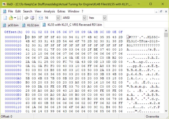
with a hex editor. Additionally, you can also change the header in the hex
editor, so you can keep track of your file versions.
For example:
Now, you will notice it says KL55. The KL48 ecu actually contains KL55
firmware. Interesting, the Ford ECU was built by Nippon Denso in Texas.
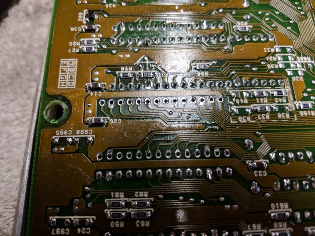
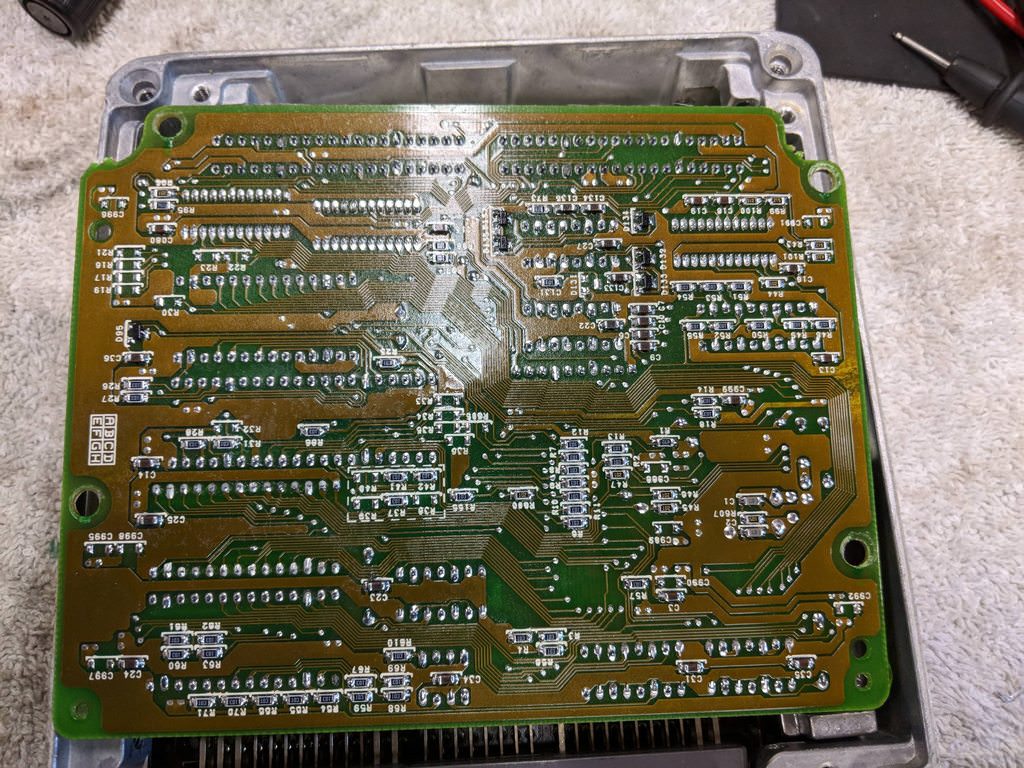
Unlike the Japanese ECUs, the circuit boards were conformally coated.
Conformal coating is a spray coating applied to circuit boards after
assembly, typically a silicone based spray. One of the main benefits is
moisture and corrosion resistance, by creating an environmental barrier.
This is a good idea for electronics in harsh locations.
To rework the board, I needed to use a specialized solvent to remove the
conformal coating. I've seen videos of guys removing the coating with a wire
brush. Do NOT do this, unless you are a ham fisted moron. After I removed
the coating, I used a solder vacuum to desolder the factory chip. For those
without an expensive rework iron, I would suggest using a very small pair of
cutters and cutting the leads off the chip. Then you can use an iron and
tweezers to remove each lead from the board individually. A bit of solder
wick later and you can have clean pads and holes. Remeber when cutting the
leads to leave a stub on the chip. You can solder headers to these, allowing
you to still dump the data off the EPROM.
All desoldered. You can see the edges of the conformal coat.
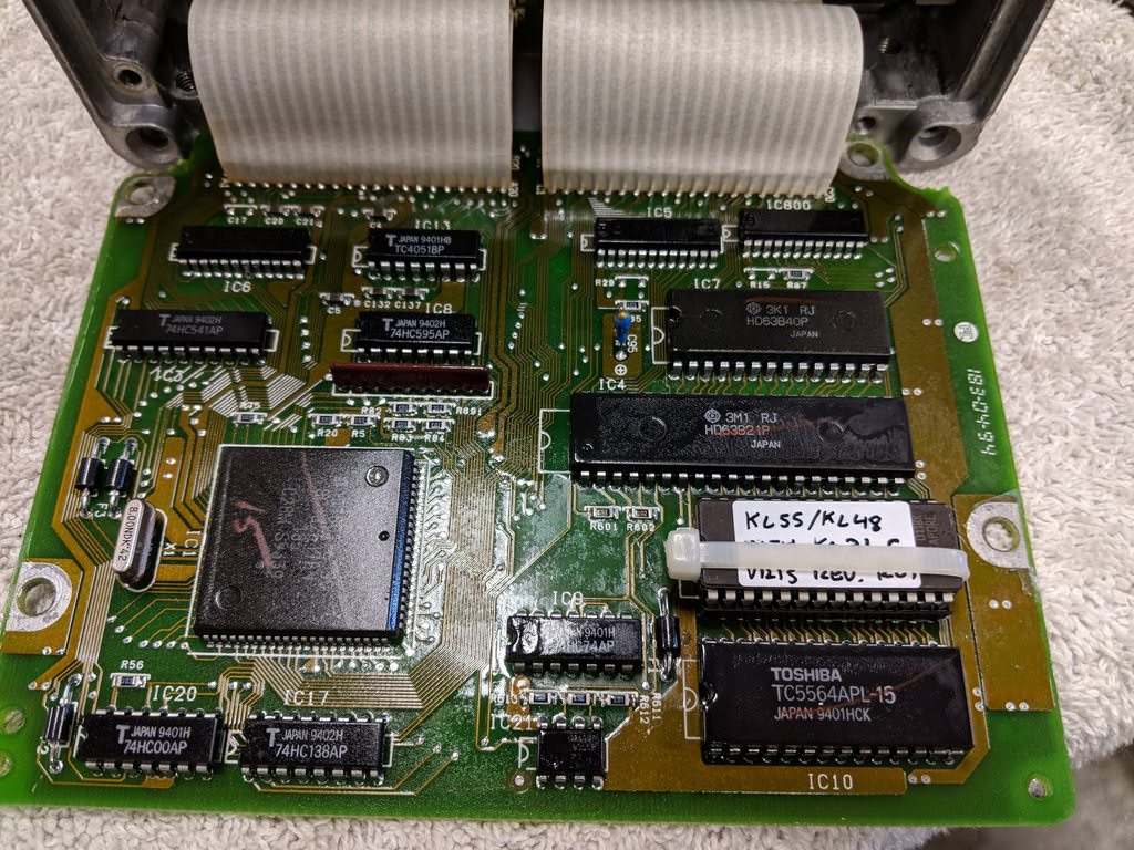
Next, toss in a socket and resolder. A quick spray of the reworked area with
conformal coating completes this mod. Make sure you mask off the socket when
you spray.
Can you see where I monkeyed with it? No? Good.
Flip it over, toss in the chip I made and we are good. The sockets I used
have provision for a zip tie, to make sure the EPROM doesn't vibrate loose.
Now, back to making the files for the chip.
Open the KL31_C.bin in the firmware editor. Make note of the VRIS table and
RPMs. We will need to manually add these to our KL55 firmware we dumped off
the chip we removed from the ECU.
Extract the fuel table, timing tables from the KL31 firmware. The modifiers
table is of a different size and can't be transfered over.
KL31 High Timing: 78 96 AF C0 CD D0 C9 C7 BC C4 C7 D2 D3 D5 78 96 AF C0 CD D0 C9 C7 BC
C4 C7 D2 D3 D5 74 96 AB B6 C7 CF C5 C4 B7 C2 C5 D0 D2 D3 6B 7D 9B A3 B8 C9
BC BC AA BF BF CD CE CD 5A 78 91 9A A6 BD B3 B3 A0 B6 B2 C7 C8 C4 52 73 8A
92 9F B3 AD AA 9A A9 AA C1 C1 BB 4C 70 87 8F 9B AC A7 A4 95 A0 A3 BA BB B2
48 6D 83 8C 99 A7 A5 A4 95 99 9E B2 B6 B0 43 6A 7F 8A 95 A2 A2 A2 94 97 9B
AC B3 AF 3E 68 7C 87 92 9E 9D 9D 93 96 9A A9 B1 AE 2B 5E 78 82 8F 99 98 96
90 95 99 A6 AE AC 2B 5E 62 74 7D 96 8F 92 8C 93 98 A5 AA A9 2B 5E 62 74 7D
7D 81 8B 87 91 95 A4 A2 A7 2B 5E 62 74 7D 7D 81 8B 84 8F 93 A2 A0 A7 2B 5E
62 74 7D 7D 81 8B 84 8E 93 A2 A0 A7
KL31 Low Timing: 78 96 AF C0 CD D0 C9 C7 BC C4 C7 D2 D3 D5 78 96 AF C0 CD D0 C9 C7 BC
C4 C7 D2 D3 D5 74 96 AB B6 C7 CF C5 C4 B7 C2 C5 D0 D2 D3 67 7D 9B A3 B8 C9
BC BC AA BF BF CD CE CD 49 73 91 9A A6 BD B3 B3 A0 B6 B2 C7 C8 C4 3D 72 83
8F 9C B2 AB AA 9A A9 AA C0 C1 BB 32 71 82 8C 9B A6 A1 A0 92 A0 A3 B6 B9 B4
31 6B 7E 8A 99 A4 A0 9F 90 99 9D AF B2 AE 2F 61 75 87 95 A3 9E 9E 8E 95 98
AB AE AA 23 4C 6A 83 91 9E 97 98 8C 93 97 A7 A9 A7 23 3F 57 76 8B 98 8F 8F
88 91 95 A1 A6 A4 23 3D 49 68 7D 8F 7F 86 81 8B 93 A1 A1 9D 23 3D 49 68 7D
83 78 79 73 83 8E 9E 97 9C 23 3D 49 68 7D 83 78 77 69 7D 85 89 85 9C 23 3D
49 68 7D 83 78 77 69 78 85 89 85 9C
Now, open your KL55 bin file which you edited the header for. You can then
go through and import the fuel and timing maps. Edit the VRIS RPMs and
change their values to match the values for whatever intake manifold you are
using. Remember I told you the KL31 straight neck intake numbered the VRIS
reversed from USDM? Well instead of rewiring the harness, I just switched
VRIS1 and VRIS2 in firmware.
Now that we have made our changes, we have to correct the CRC.
There is a slight trick with the program. You will notice the checkbox
"write to beginning". To adjust the CRC, the program will change some unused
portion of the firmware to some different values, so the entire CRC checksum
matches. Some firmware versions have blank or non data at address 0x7FBE or
0x7FBF. If you determine your firmware only has checksums or empty data
around these locations, you can let the program edit those memory addresses.
Some firmware has program data in this location. Adding CRC correction
values there would cause unintended operation of the ECU, or anger the magic
pixies. In these cases, we can write to the beginning, or header area
without harm. I suspect we can probably always write to the beginning for
any firmware.
So, with that said here are the steps to correct the CRC.
1. Click "Calculate".
2. Check the "write to beginning" box.
3. Click "Adjust".
4. Click "Save".
If you did this properly, the calculated CRC box should show AA55.
Now, break out your 1980's UV EPROMs, burner and UV eraser.
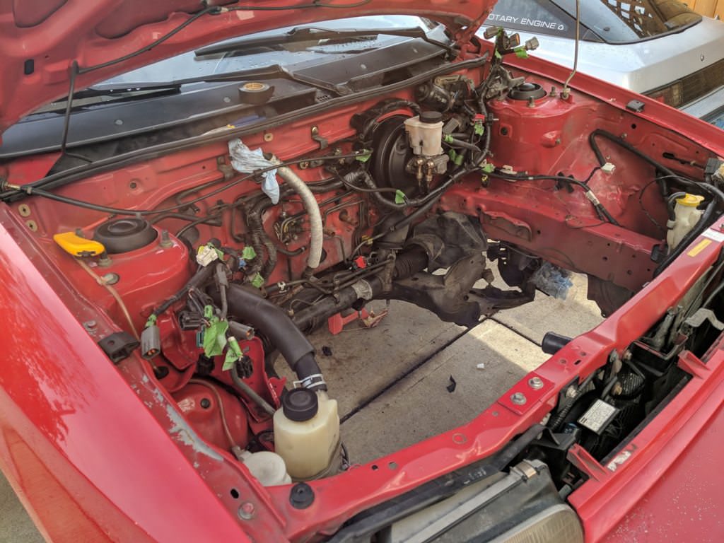
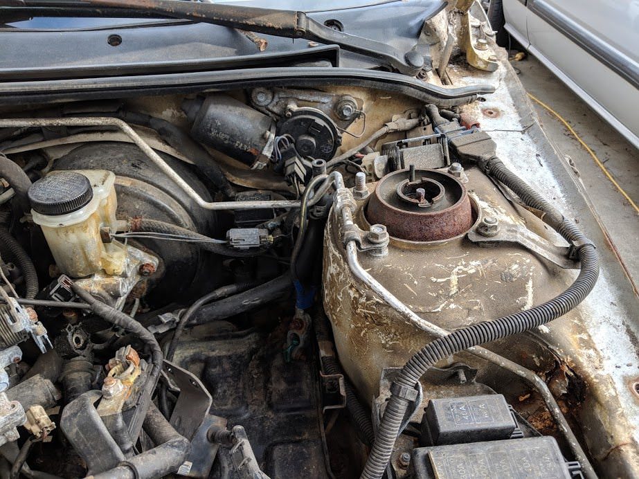
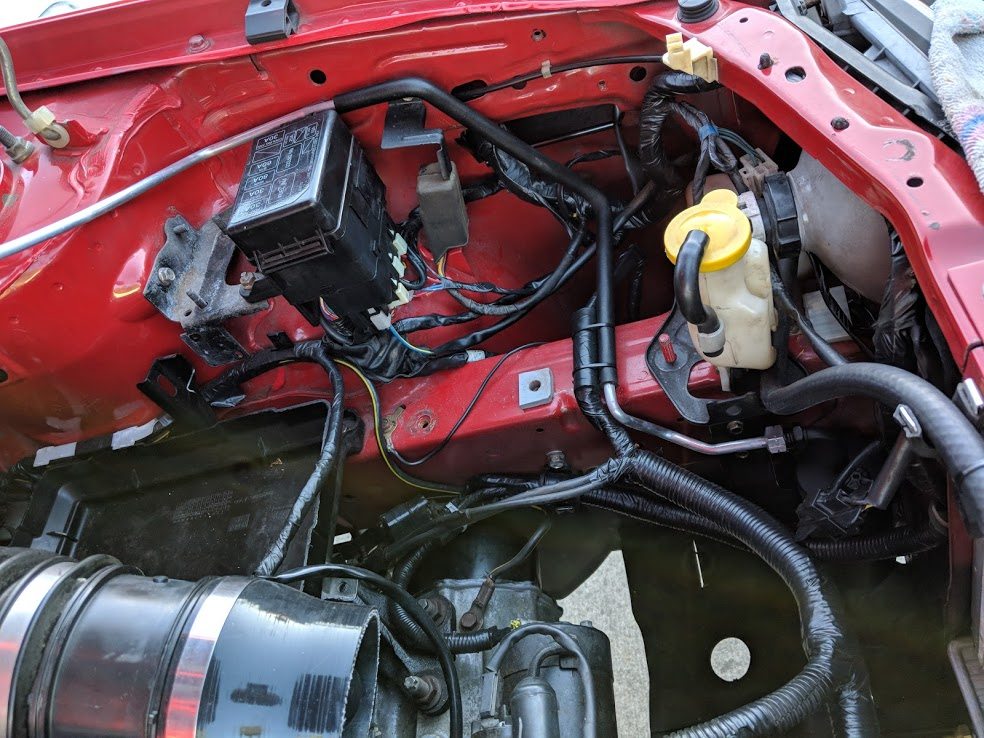
Let's put the ecu madness aside for a bit and catch up on the mechanical
stuff. We left off with an assembled engine and an empty engine bay. The
subframe had been swapped over, along with the MX-3 GS brake booster and
master, proportioning valves and brake lines.
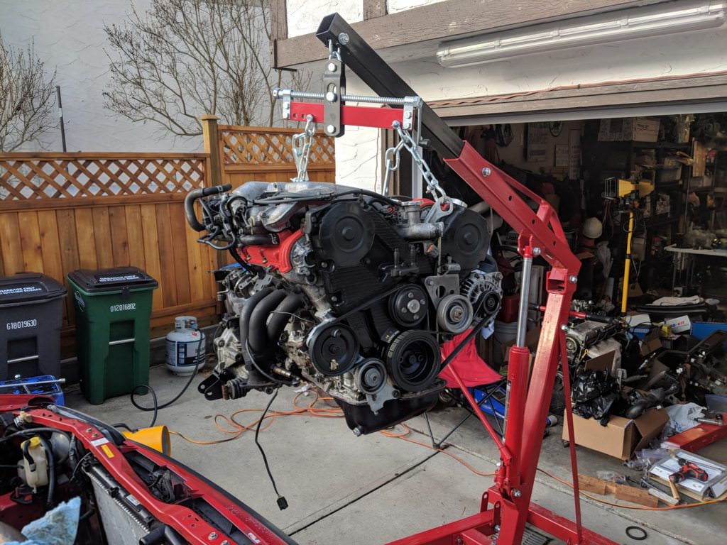
Up on the hook. I was bad about taking pictures of a lot of this. Installed
the new clutch and pressure plate.
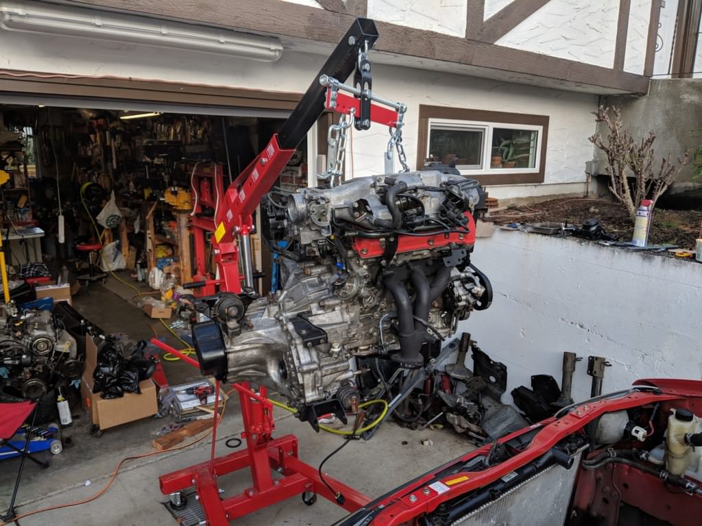
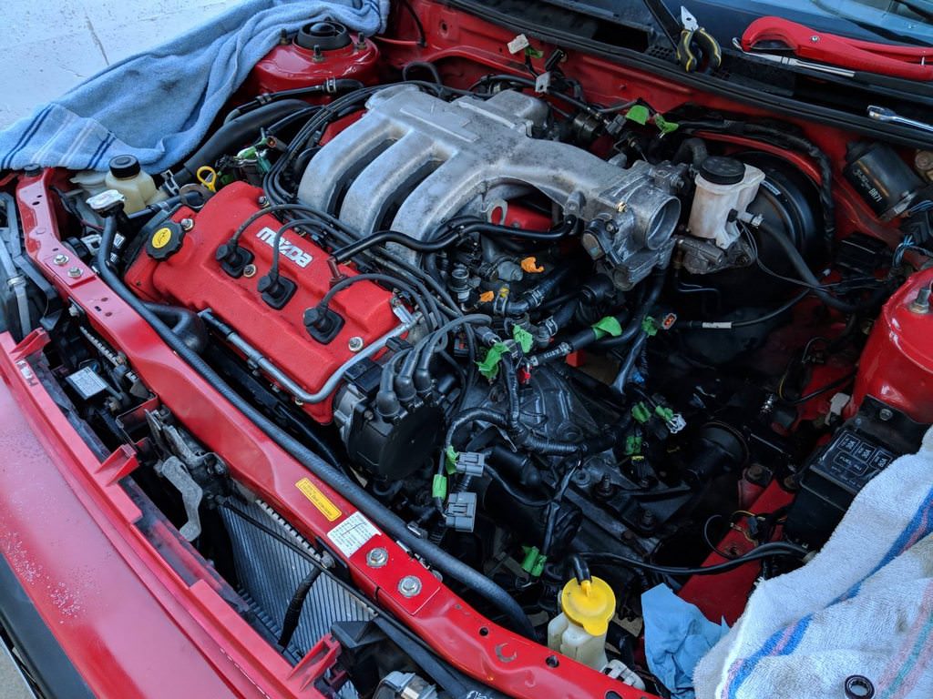
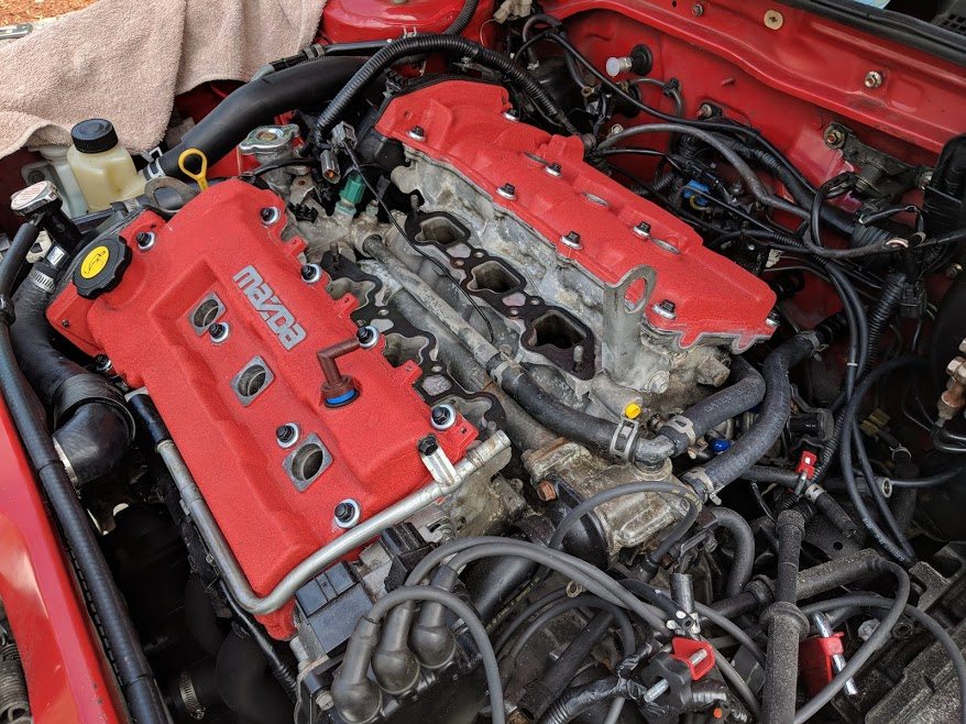
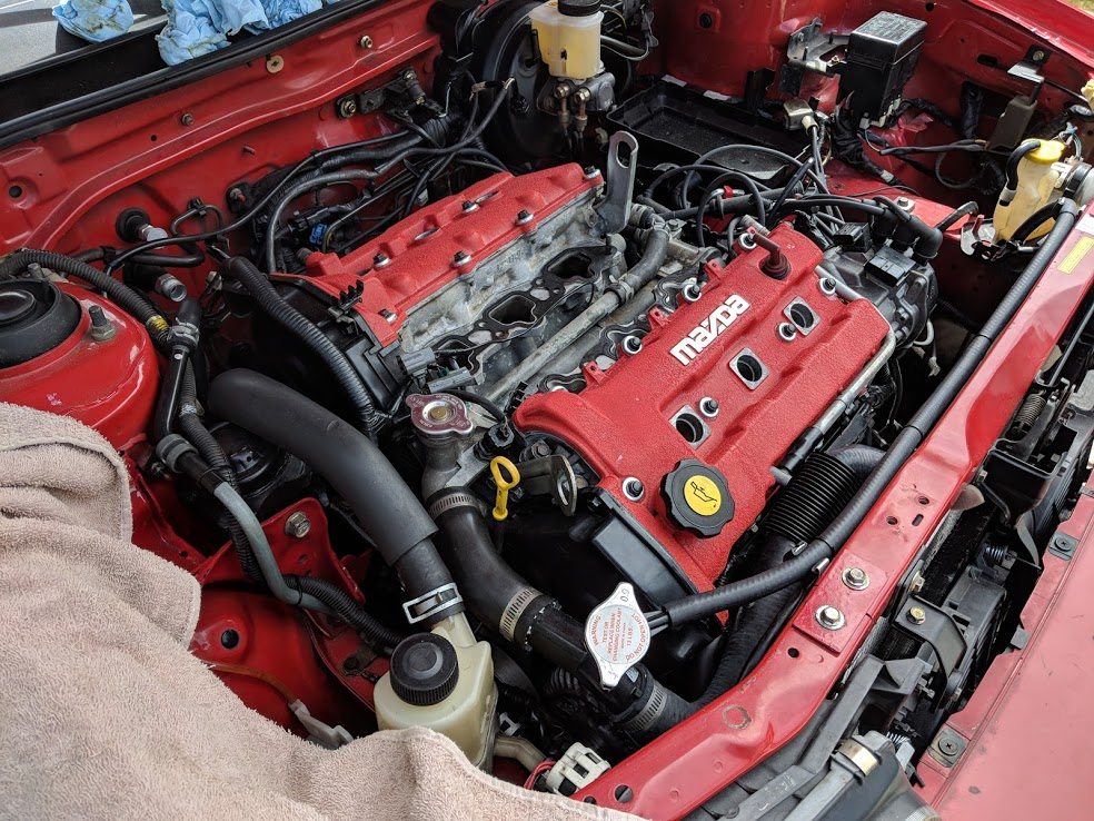
It looks really big with the transmission back on it. It really is going to
fill the engine bay.
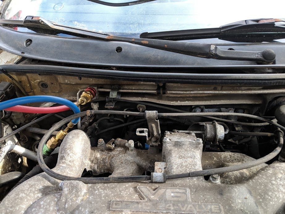
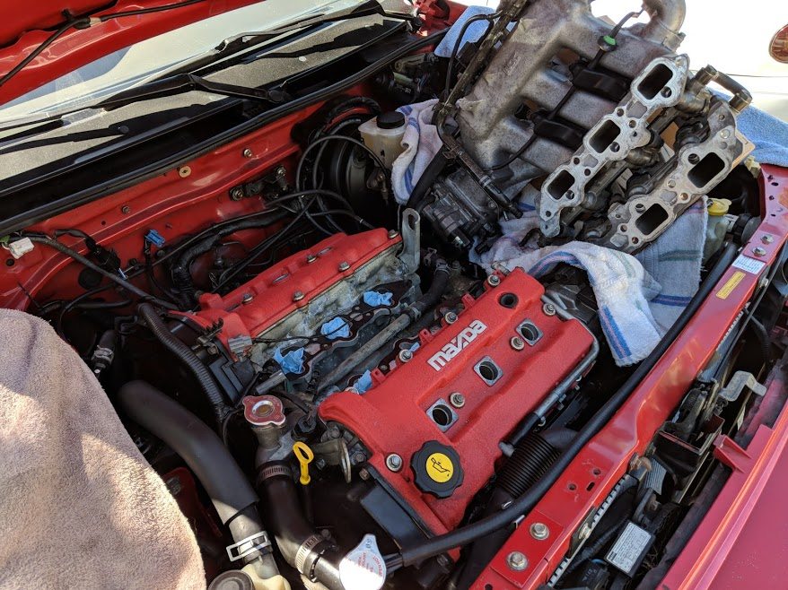
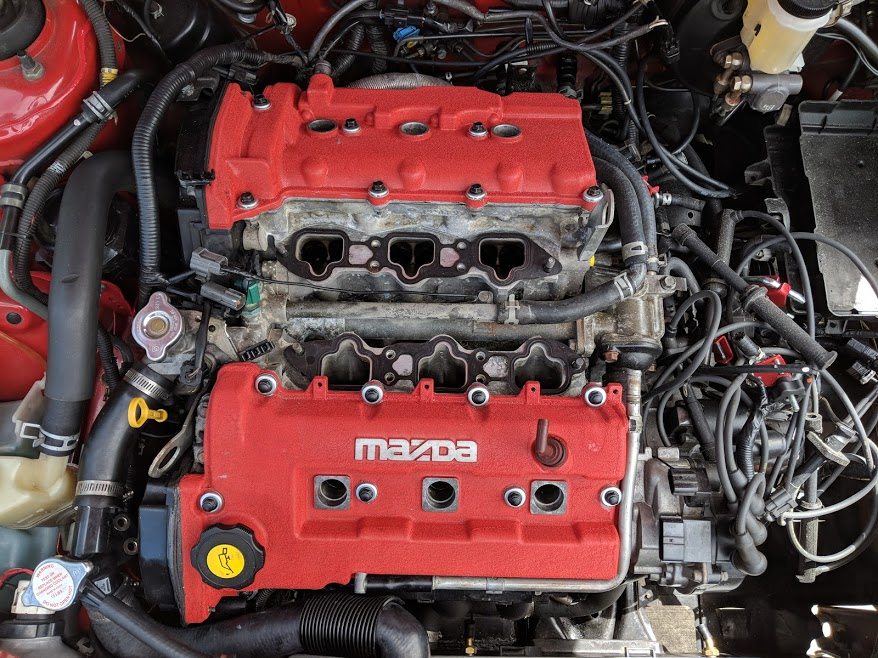
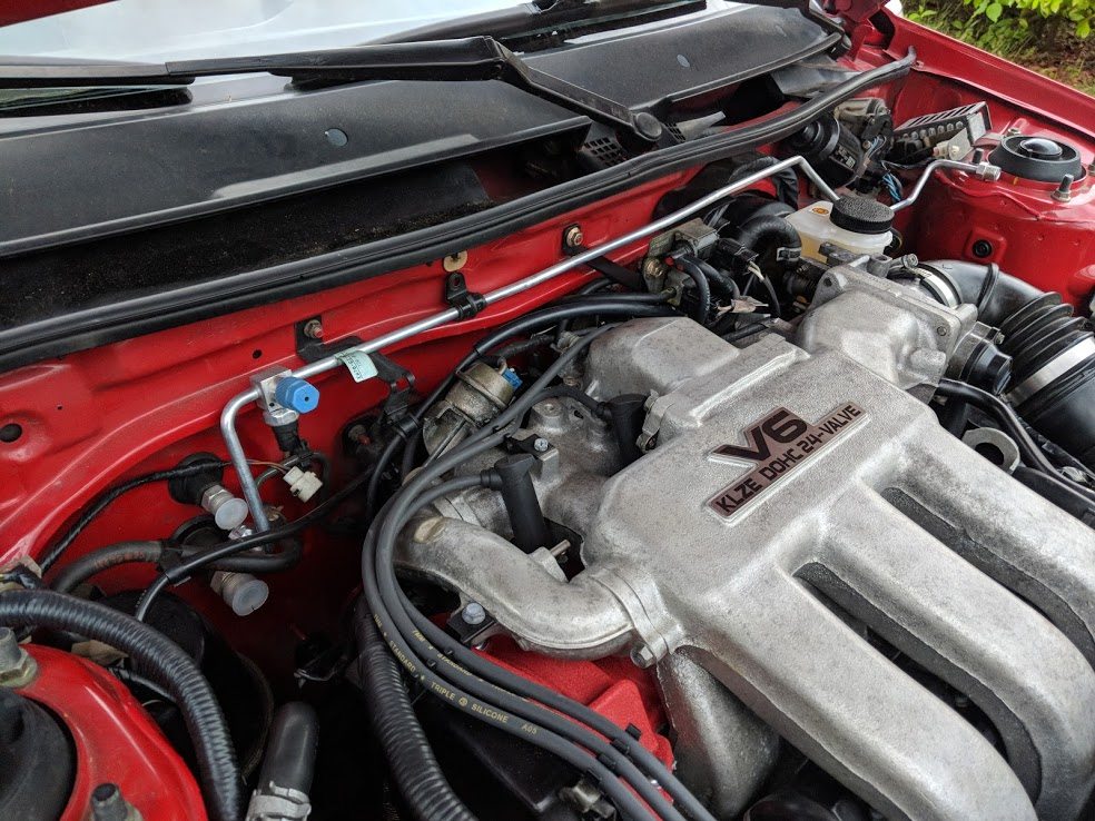
It took some wiggling and prying, but eventually the beast slotted into
place. The straight, long neck intake is the best for performance, but it
really barely fits in place. The intake manifold was touching the brake
master cylinder.
Someone had already ground the progressive throttle bell crank on the KLZE
intake to increase clearance, but the outside rolled metal part that holds
the tit on the end of the throttle cable still did not clear. I welded a
piece of metal to the inside to support the holder and then ground off the
outer radius. It just cleared.
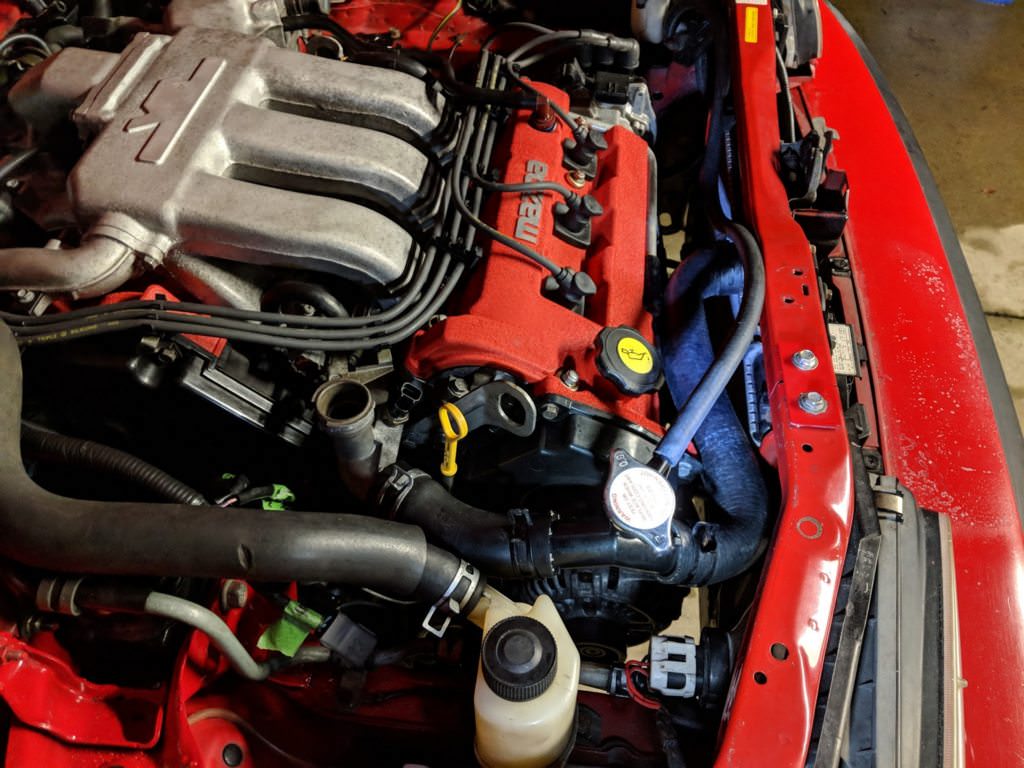
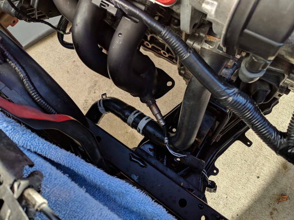
Radiator hoses were next. The KLZE coolant filler neck does not have
provision for an overflow line. On the MX-3, this is done on the radiator.
The Dodge Neon radiator was just a plain input and output. To deal with
this, I did some rockauto browsing and settled on a filler neck from a
2008-2018 Toyota Yaris (part# DORMAN 902680). Unfortunately, the Yaris uses
a higher pressure rad cap, which is also a different size. The 1995-1997 Geo
Metro uses the same pressure as the KLZE, but fits on the Yaris filler
(part# STANT 10241). Great!
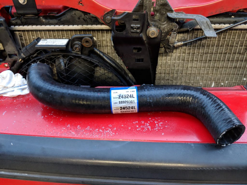
Hoses were a bit of a pain. I made some templates and headed to the local
parts store. After digging through their hoses for an hour, I had something
which would work. Top hose was from a 2004-2010 Chevy Aveo (the lower hose)
(part# ACDELCO 24524L)
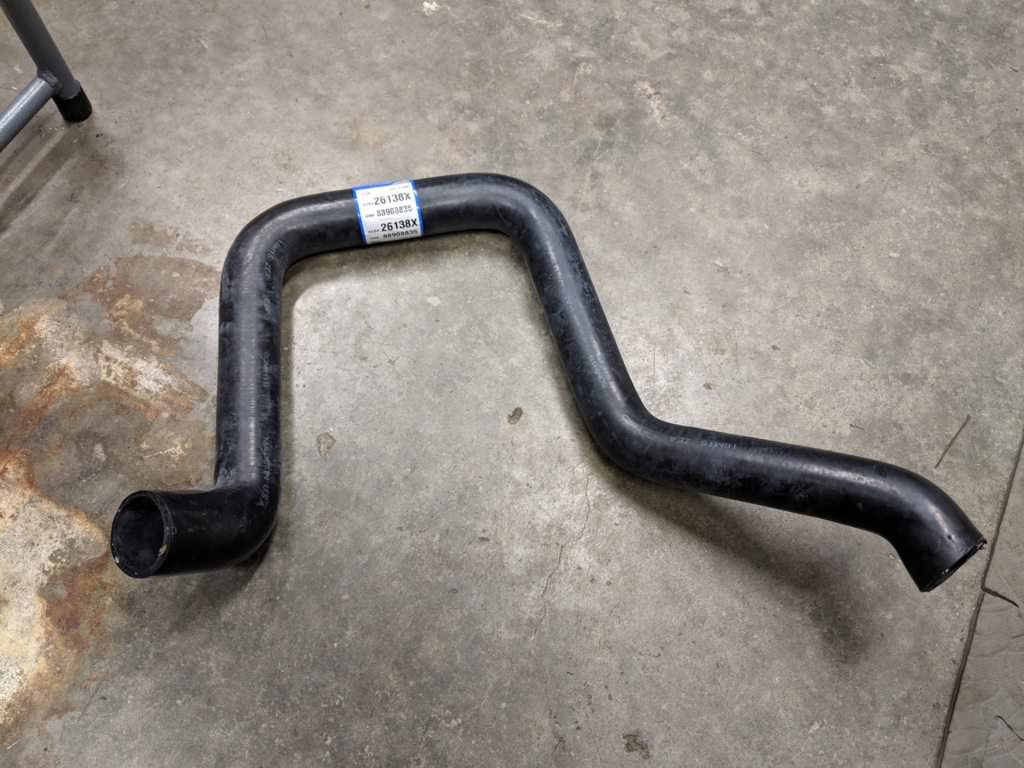
Lower hose was a bit more trouble. I used the upper hose from a 1987-1992
Jeep Comanche (part# ACDELCO 26138X). I had to cut the hose and use a
coupler to change the angle. It worked pretty well.
Now that I had a cooling system, I really started getting excited about
hearing this thing run, or at least wondering if it actually would.
Naturally, the logical solution was to start tossing the bare minimum on to
get it to kick over. I filled up the fluids, tossed on the VAF sensor and
connected up a battery.
Here is the first crank, open headers etc. The HLA are ticky since they have
not primed.
It runs. I don't think I've ever had an engine start up that smoothly,
though normally I am dealing with freshly rebuilt rotaries. Not too bad, but
holy jesus it was loud.
Which leads me to the next task, exhaust.
The engine had come with an ebay special header kit. It was pretty crusty
and as I learned later, was made for a 626. This meant the O2 sensor bungs
were in the wrong place and would hit the steering rack. Someone had welded
new bungs in, but they were even worse, they would hit the carrier bearing
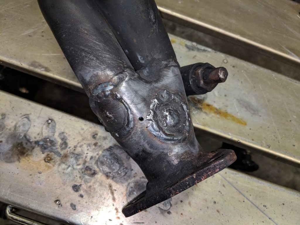
for the intermediate shaft of the trans. Time to get the hole saw out.
Interestingly, the perfect location for the sensor would be exactly in the
middle of the two other bungs. I used the next size up of hole saw to cut
out some patches, and then welded them in. Not sure why the welds look so
terrible, but I was trying to fill some large gaps. You can see the pilot
hole for the correct bung location.
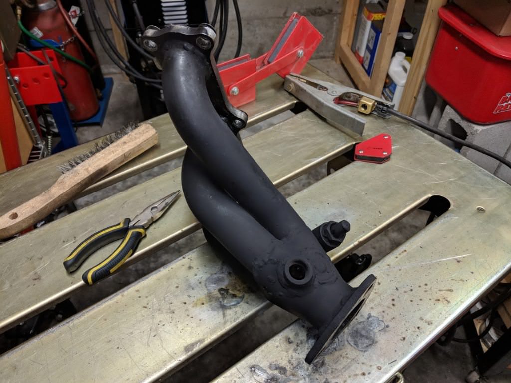
Bung welded and the entire piece painted with ceramic paint.
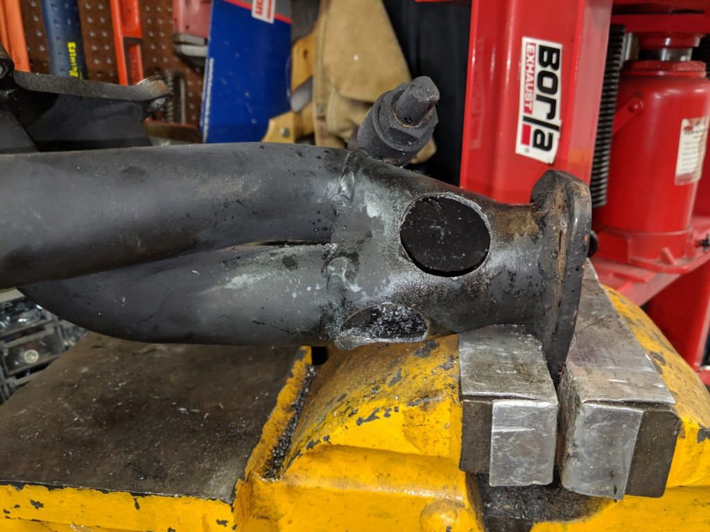
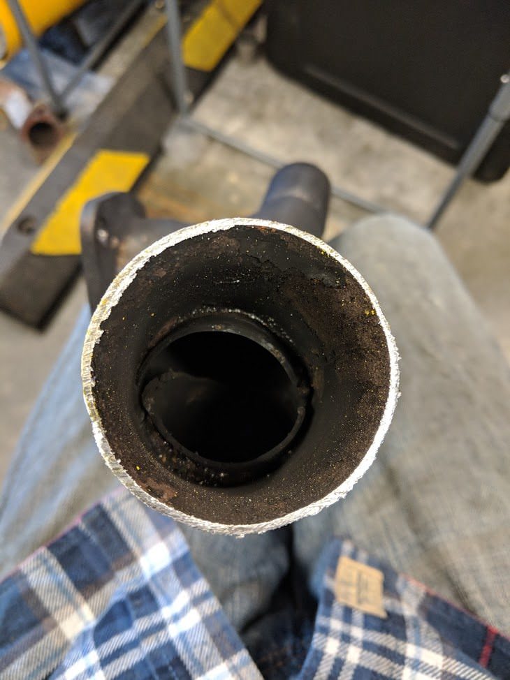
Now, onto the collector. The ebay collector looked good, but the pipe sizes
were a bit odd. The runners were 1 7/8" which collected into a 2" pipe, into
a 2.5" flex and out to a 2.5" pipe, to match the cat inlet. I had decided on
2 1/4" exhaust, so it didn't make sense to choke it off to 2" at the
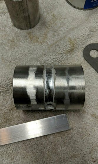
collector. Out came the hacksaw and I was shocked at what I found.
It is a bit hard to see, from the soot, but they didn't trim the ends of the
pipes at all inside the collector. I measured the opening, a tiny 1 1/4"
opening. Out came the rotary file and I smoothed up the mating of the
runners. I also welded on a new 2.5" pipe into the flex section.
I also took the opportunity to weld in a bung for the wideband sensor I had
borrowed. I only plan to run the wideband while tuning the ecu.
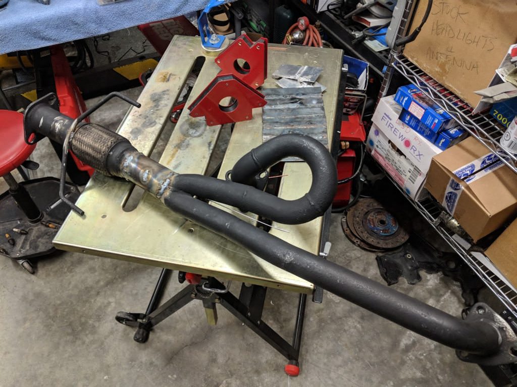
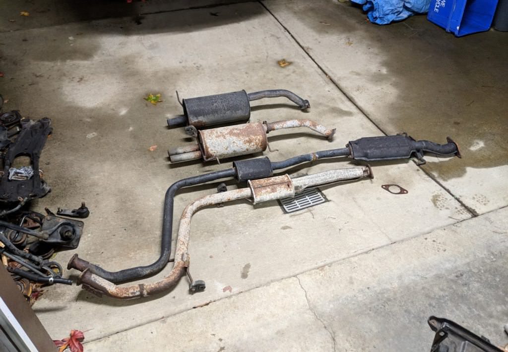
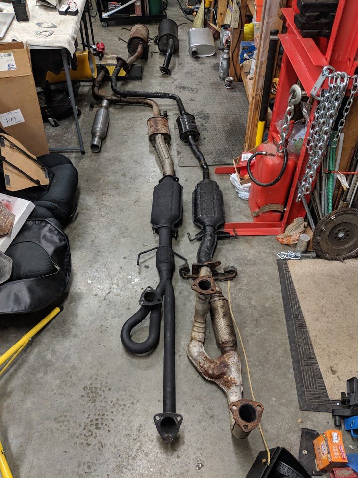
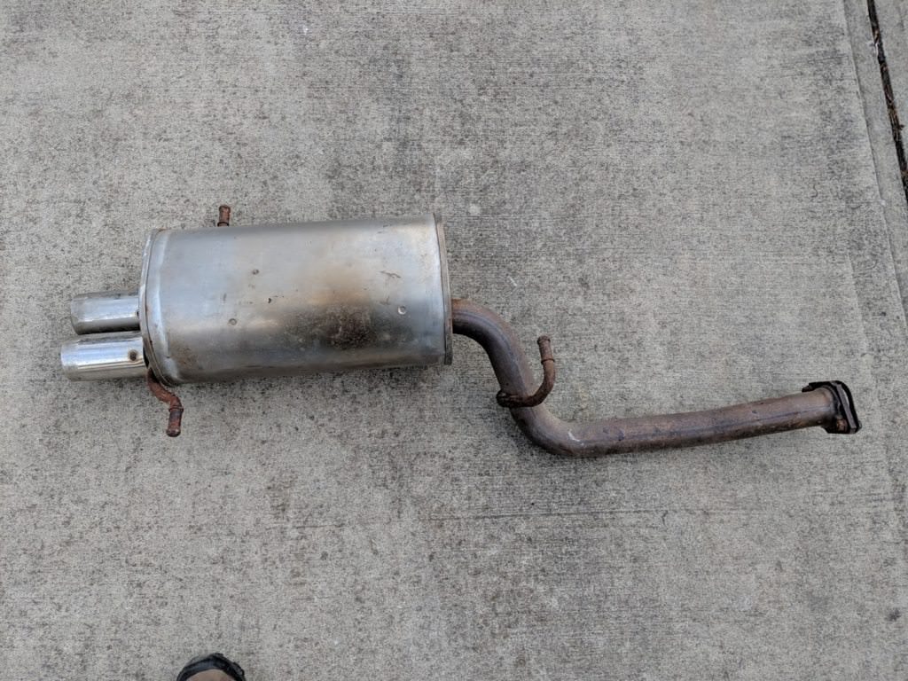
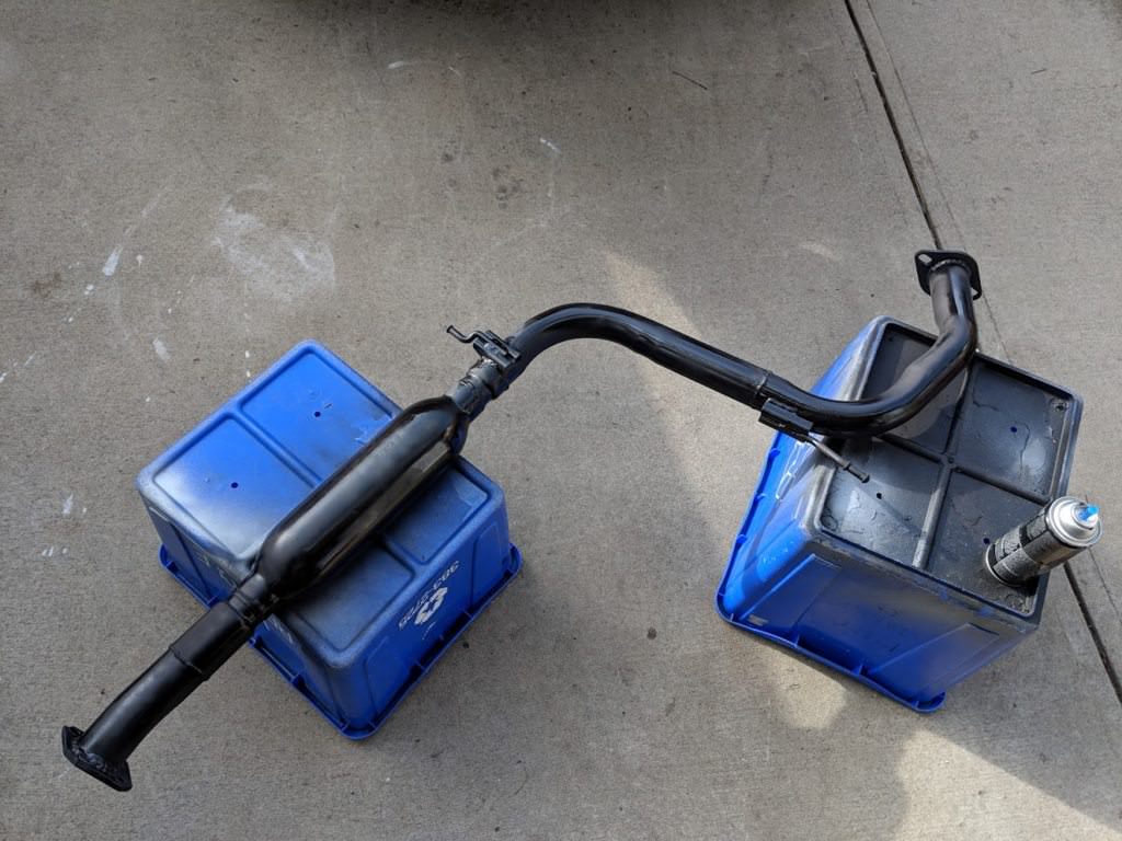
I laid the MX-3 exhaust out beside the 323 to get an idea of length and
shape. The 323 is the black pipe. The 323 is 1 7/8" while the MX3 is 2"
You can see they are very similar, the portion from the cat back is exactly
the same. The difference is in the cat itself and the pipe ahead of that.
The 323 has a longer outlet on the cat, whereas the MX-3 takes up this
length in the collector. Given that I had a 626 collector, I would have to
make something custom anyway.
I got a universal 2.25" resonator and muffler and started trying to figure
out routing.
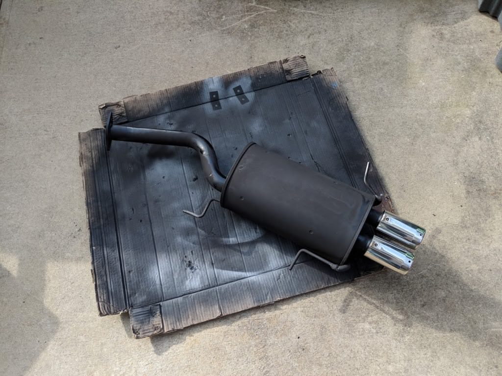
Honestly, I wasn't a fan of the muffler. It didn't fit as well as I would
have liked, so I sent it back. A coworker had a spare WRX muffler laying
around, which looked like it would work well, was 2.25" and stainless.
Besides, it fit the theme of using parts from other cars.
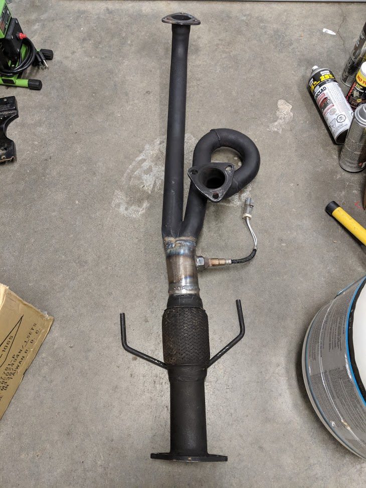
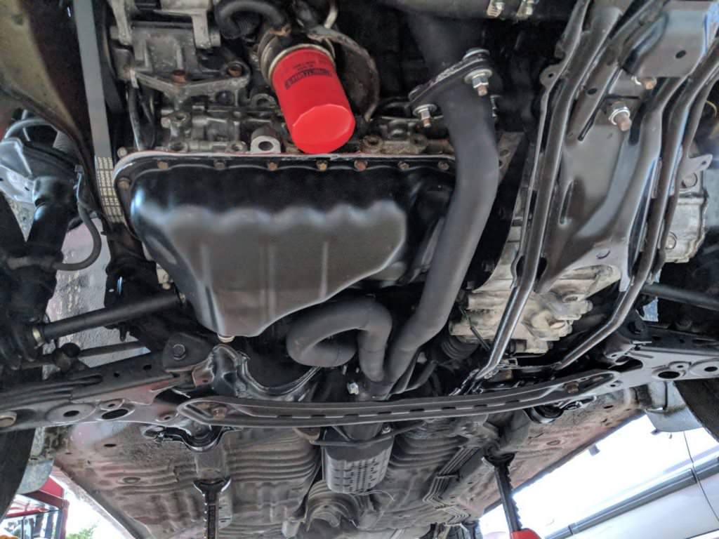
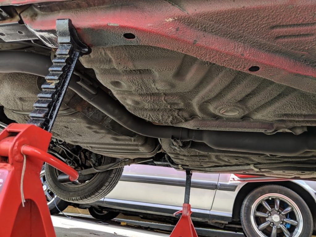
I installed the collector and cat to start the mock-up. I really like how
the collector fits in, coiling into the oil pan.
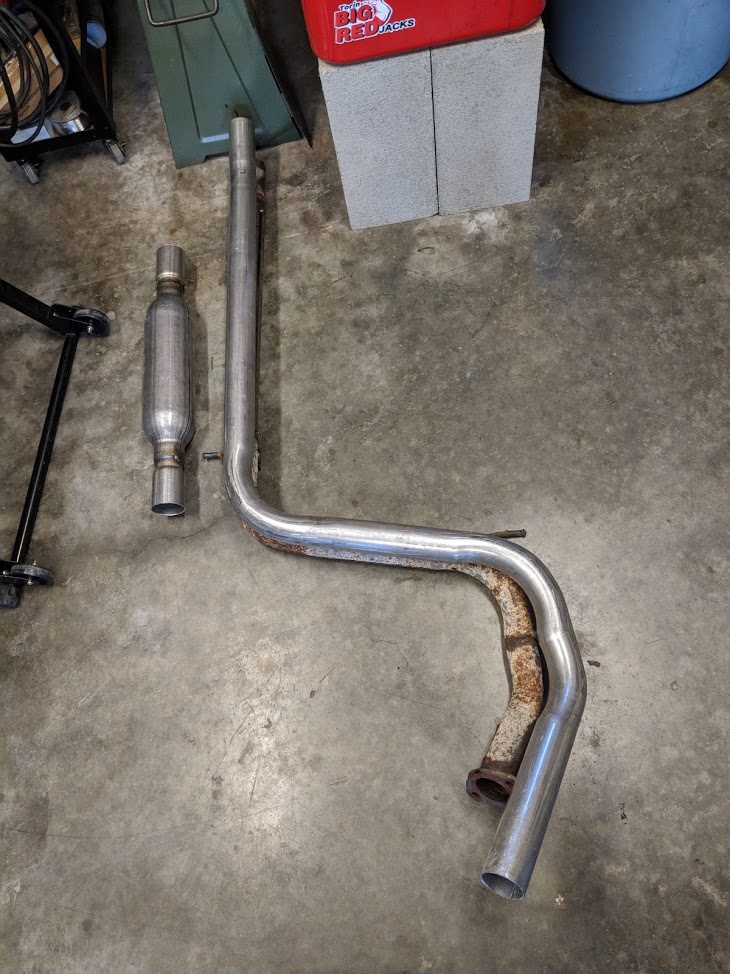
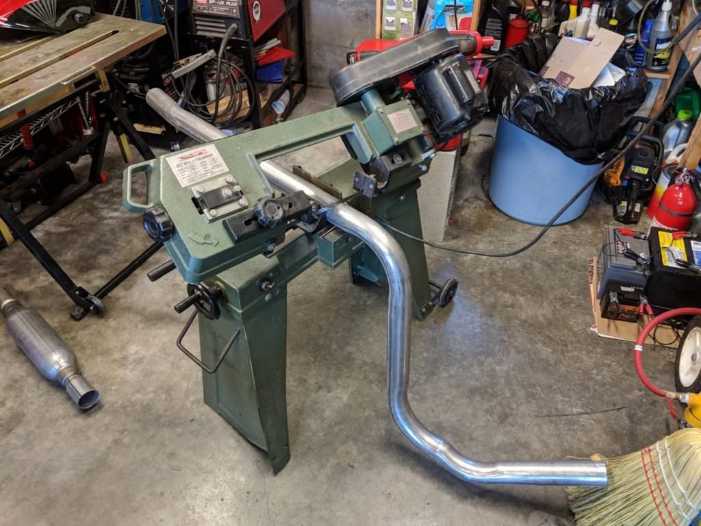
There is a local muffler shop which still bends up pipe (Island Muffler in
Victoria). I welded up a template using the old pipe and took that in to
have bent in 2.25". When I went in, there was a line of people dropping off
their cars for the day. When it was my turn, they asked what I wanted, to
which I smiled, held up my rusty pipe template and said "I want this, but
bigger". I was probably the most unusual job that day. They did a good job,
and were cheap, but missed a dimention slightly. No worries, cut and weld.
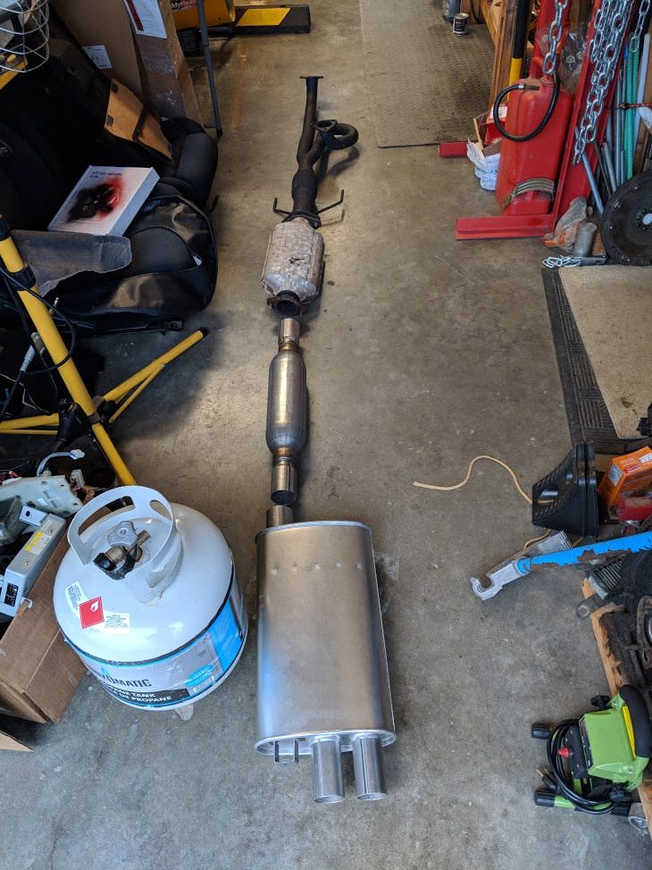
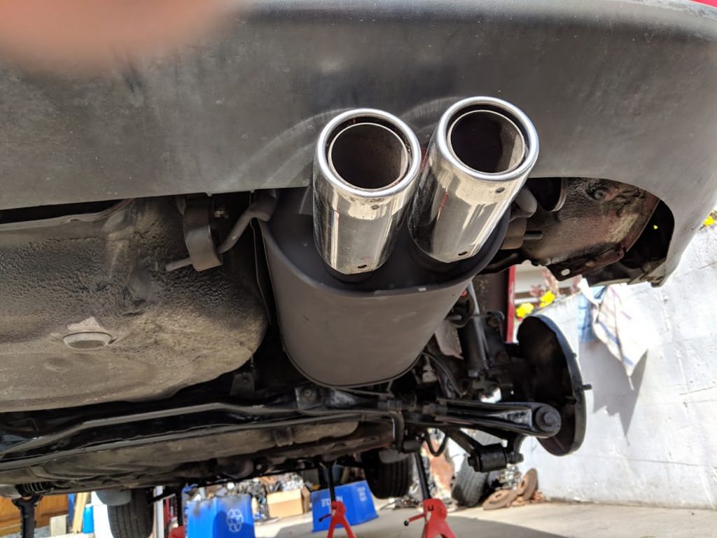
Some paint and welding later and I had this:
The exhaust was definitely one of the most time consuming parts of the
build. I am quite happy with how it turned out. It sounds very very quiet,
with a low rumble. Its quiet enough that if you were not paying attention,
you would just ignore it, but as you accelerate through the gears it sounds
deep, mute and rumbley, and lets you know something isn't quite normal.
Hopefully people are not getting 'exhausted' with this build. Oh well, I
will just reply to myself ;)
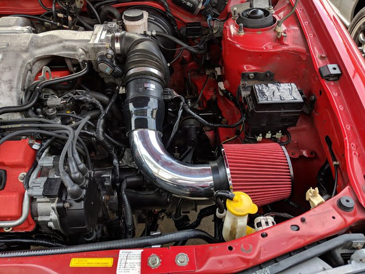
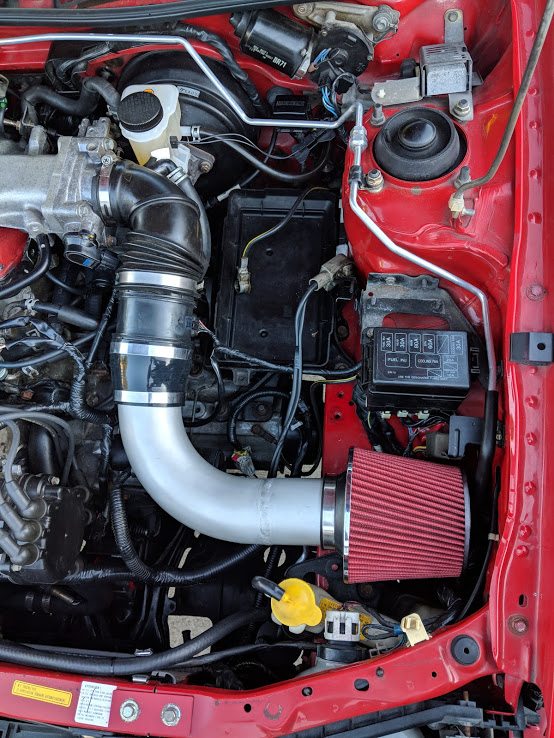
So now that the exhaust was sorted, it was time to figure out an intake.
The stock K8 flex coupler and VAF take up a lot of room. This is the
straight neck KLZE intake which is the hardest to fit in, but flows best.
Most people who swap these engines into MX-3s use a curved neck to clear the
battery better.
I mocked up a filter, silicone reducer and 90 degree pipe.
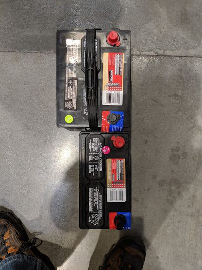
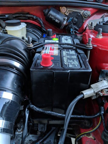
Not too bad, but the stock battery was definitely not fitting back in there.
Time to go battery shopping at costco.
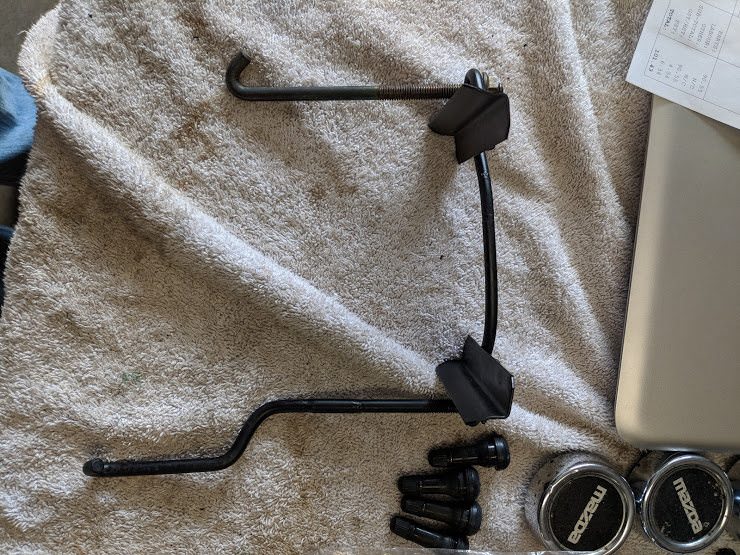
Top is the stock 323 battery (group 35). Bottom is a group 51R, used in
modern Hondas. Height and length are pretty similar. Width gives me enough
room for the intake piping.
I wasn't happy where the filter was sitting. The stock pickup scoops air
from the fender area. I also needed some sort of a support for the filter
end; it was too floppy otherwise. I've never welded aluminum before, but
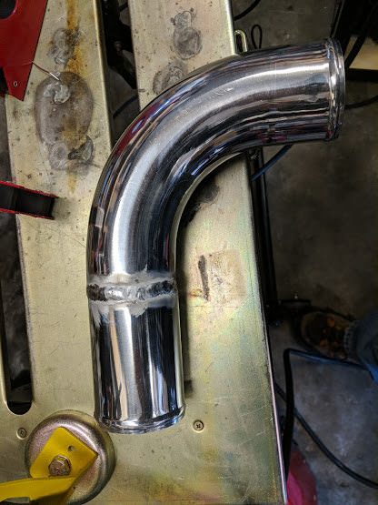
figured I might as well put my TIG to good use.
I took some scrap pipe and after four or five tries I had this:
Okay, looks decent enough, let's try the real thing.
A little rougher, but not too bad. For whatever reason I needed to use a lot
more filler rod on this tubing than my practice piece.
It fits in nicely with the new battery. I also welded a support bracket to
the underside.
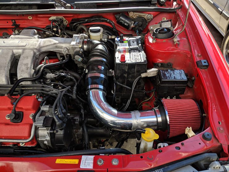
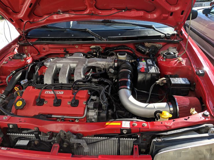
The polished pipe has to go. Nothing else is shiny in the engine bay. I
glassbeaded and clearcoated the pipe. It looks a lot more like cast aluminum
now. Hard to capture in the pictures.
I also modified and shortened the 323 battery hold down. I had to extend one
side, add some new bends and shorten the top piece.
I had a Honda battery box laying around. It also fit well and made
everything look more finished and factory.
Let's step back from the mechanical stuff for this post and revisit the ECU
maps. If you remember, the MX-3 ECUs (K8) had different dimensioned fuel and
timing tables than the KLZE (KL31) Japanese ECUs.
For example, here is the high timing map from a K801:
15x17 in size.
Here is the KL31:
14x15 in size.
Obviously you can't copy the Japanese map into the K8 ECU. This got me
thinking. I figured there are two possible reasons for the table size
difference. One reason could be that the K801 table has a greater range of
values, ie, it has data for higher RPM and higher load. I would have
expected the KLZE ecu to have more RPM range, not the little 1.8L ecu. The
two tables look very close in shape, it does not look like they added data
on the upper end of the ranges. That leaves the other explanation, that the
K8 ECU has a higher resolution on load and RPM. Again, not sure why, but it
seemed the most likely option. This is obviously all guesswork.
If we suppose that the K8 has the same range in the table, but just more
data points, that means we have to take the KL31 ECU map and linearly expand
it. Think of it like stretching a quilt evenly in size. You have the same
pattern, but it occupies more space.
How can we do this? Like most of life's problems, this one can be solved
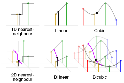
with maths. Enter bicubic interpolation. This is a method of calculating
data points based on their neighbors in a 2D array.
You can get an idea from this (black dot is the interpolated value):
Cubic takes the values of more than it's immediate neighbours into account.
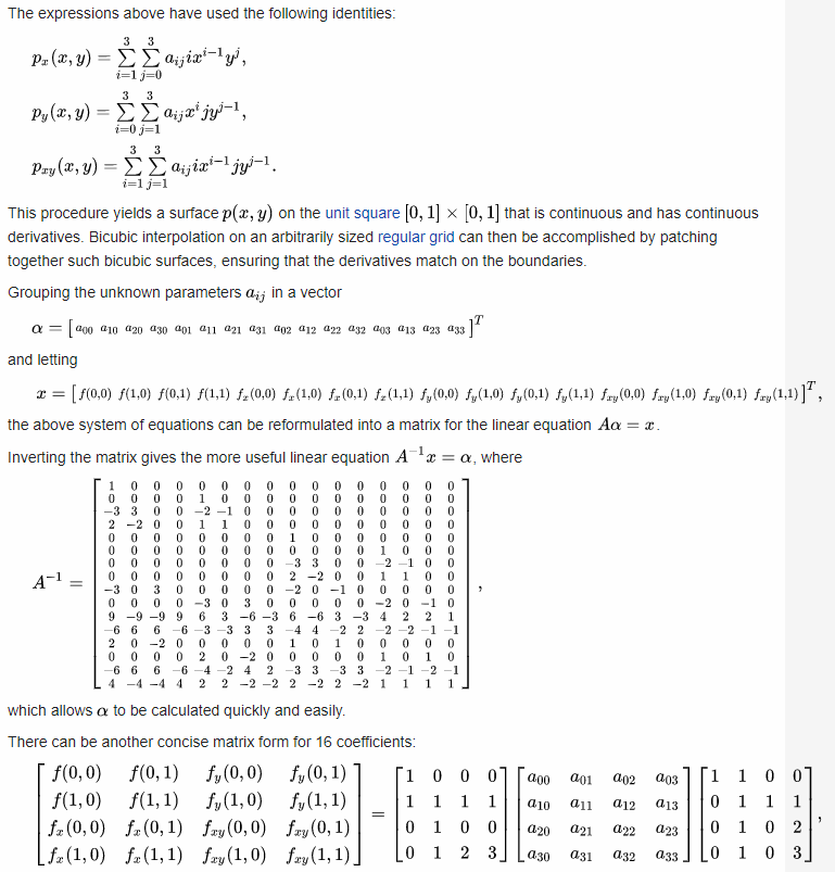
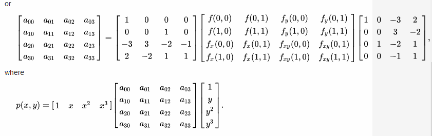
Wikipedia walks us through the math:
Yeah, so I'm an Engineer, not a Mathematician and I've conveniently 'lost'
my copy of Matlab from university, so let's think of an easier way. What
uses bicubic interpolation? Image processing! I bet there is a library for
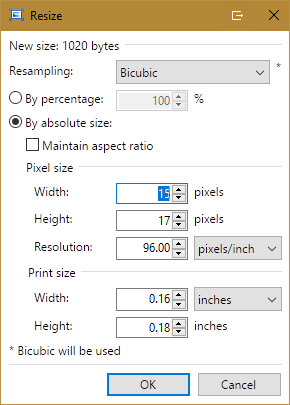
performing this on an array. In fact, Paint.net has this as an option when
resizing images..
Great, well I'm sure I can find the source code somewhere. Then I got to
thinking. A bitmap image is technically an array of pixels, where a set of
values represent each pixel.
For an 8-bit monochrome bitmap image, the image is broken down into an array
of 8 bit (or 1 byte) pixels. Each pixel stores the gray level, ie, a value
from 0-255. (For a colour image, you will have three bytes per pixel, for
red, green and blue levels) Conveniently, the timing value is also 1 byte,
or 0-255, 0x00-0xFF.
So, I could easily write a program to create a 8-bit bitmap with the gray
level data as the values from my timing array.
So, this:
[code]
78 96 af c0 cd d0 c9 c7 bc c4 c7 d2 d3 d5
78 96 af c0 cd d0 c9 c7 bc c4 c7 d2 d3 d5
74 96 ab b6 c7 cf c5 c4 b7 c2 c5 d0 d2 d3
67 7d 9b a3 b8 c9 bc bc aa bf bf cd ce cd
49 73 91 9a a6 bd b3 b3 a0 b6 b2 c7 c8 c4
3d 72 83 8f 9c b2 ab aa 9a a9 aa c0 c1 bb
32 71 82 8c 9b a6 a1 a0 92 a0 a3 b6 b9 b4
31 6b 7e 8a 99 a4 a0 9f 90 99 9d af b2 ae
2f 61 75 87 95 a3 9e 9e 8e 95 98 ab ae aa
23 4c 6a 83 91 9e 97 98 8c 93 97 a7 a9 a7
23 3f 57 76 8b 98 8f 8f 88 91 95 a1 a6 a4
23 3d 49 68 7d 8f 7f 86 81 8b 93 a1 a1 9d
23 3d 49 68 7d 83 78 79 73 83 8e 9e 97 9c
23 3d 49 68 7d 83 78 77 69 7d 85 89 85 9c
23 3d 49 68 7d 83 78 77 69 78 85 89 85 9c
[/code]
becomes:
Which means I can now load it into Paint.net and resize it to 15x17 pixels.
We can then run it back through the bitmap to bit array program we wrote to
get:
[code]
77 92 AB BC C9 D0 CC C8 C2 BD C5 C9 D2 D3 D5
77 92 AB BC C9 D0 CC C8 C2 BD C5 C9 D2 D3 D5
74 93 AA B6 C5 CE CA C5 BF BA C3 C7 D0 D2 D4
6E 84 9D A7 B8 C8 C5 BF B7 B3 C1 C4 CE CF CF
62 75 91 9B A8 BD BD B7 AE AA BB BB CA CA C7
55 72 8A 95 9D B2 B5 B0 A7 A2 B0 B1 C6 C4 BF
4F 6E 86 8E 98 AB AE AA A0 9B A6 AB C0 BE B7
4A 6B 83 8C 95 A6 A9 A5 9C 96 9F A6 BA B9 B0
47 69 80 89 94 A2 A6 A5 9D 94 99 A1 B3 B5 AF
42 66 7C 87 91 9D A2 A2 9C 93 97 9E AD B3 AE
3F 65 79 84 8E 9A 9F 9E 99 93 96 9C AA B1 AD
2F 5C 76 81 8D 97 9A 99 94 91 95 9B A7 AF AB
27 58 69 76 81 92 96 93 91 8F 94 9A A6 AC A9
29 5A 5F 6E 78 86 8A 8B 8C 8B 93 98 A5 A6 A7
29 5A 61 70 7B 7B 7C 85 88 87 91 96 A3 A0 A6
29 5A 61 70 7B 7D 7E 86 87 85 8F 94 A1 9F A7
29 5A 61 70 7B 7D 7E 86 88 86 8E 95 A2 A0 A7
[/code]
An array of 15x17, which can be stitched into the K8 firmware.
You will notice it shares the same shape/magnitude as the smaller KL31 map,
just stretched or interpolated over a larger number of points.
So, I have no idea if my assumptions are correct, but it at least gives a
bit of insight into my insanity.
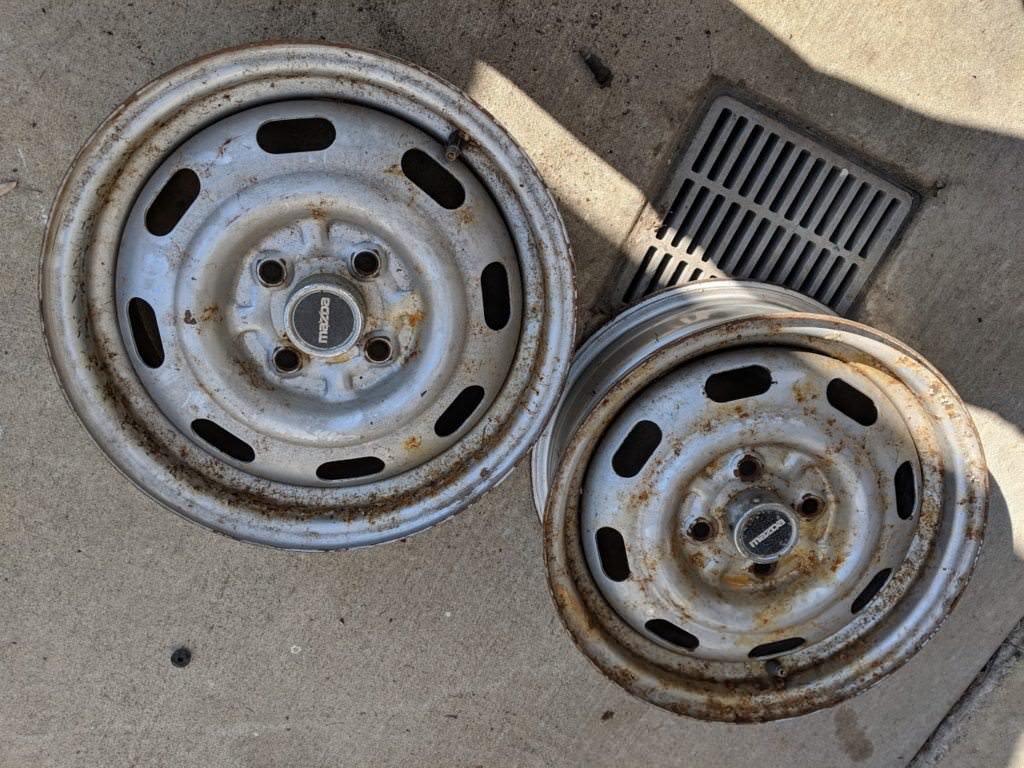
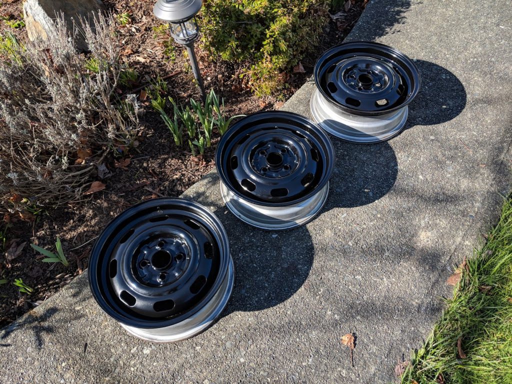
In the interest of looking like a bone stock car, I picked up a set of
14" miata steel wheels with Mazda center caps for $40.
They were pretty ugly. A quick sandblast and coat of paint later however,
they looked alright:
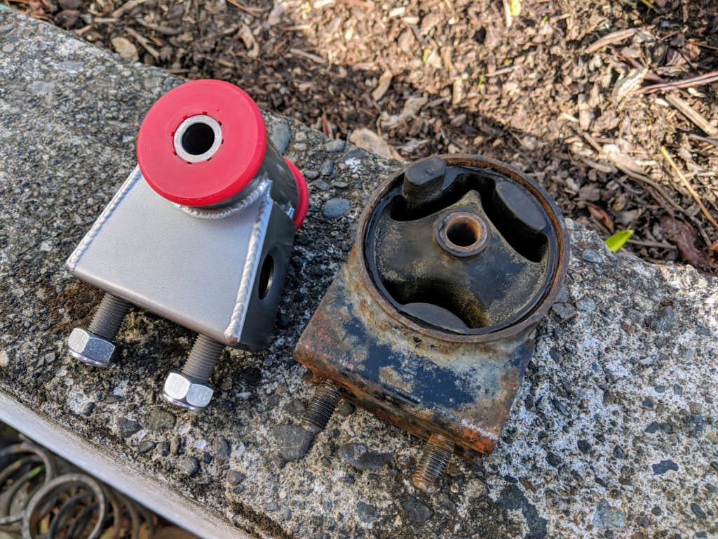
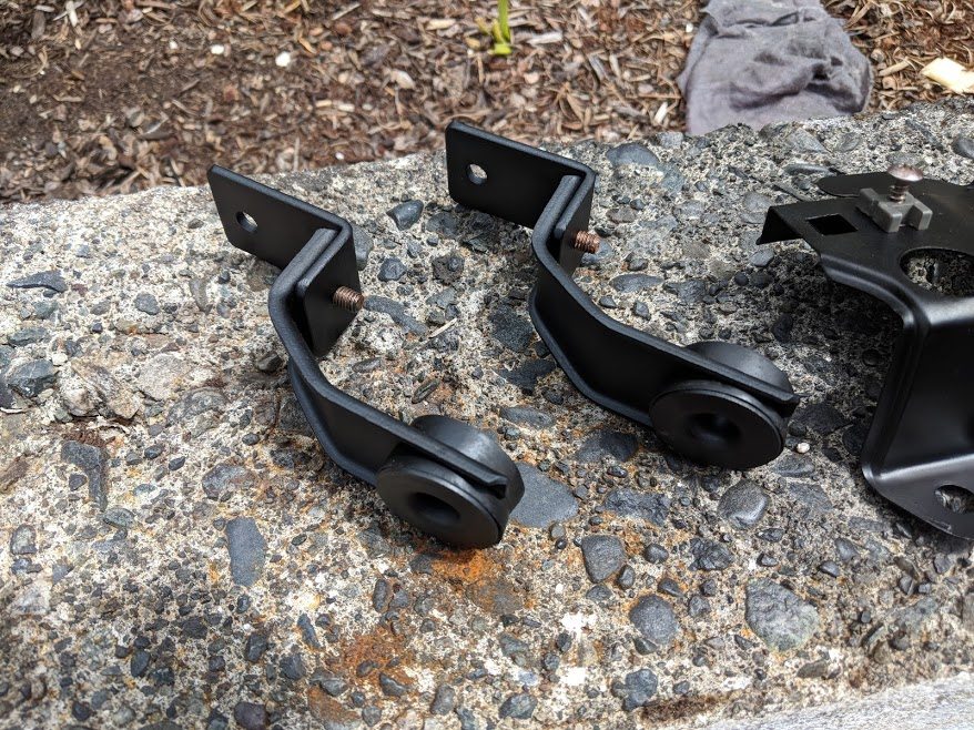
Someone was asking earlier about motor mounts and tight tolerances. These
were the mounts I used, from AWB. They really don't have much flex.
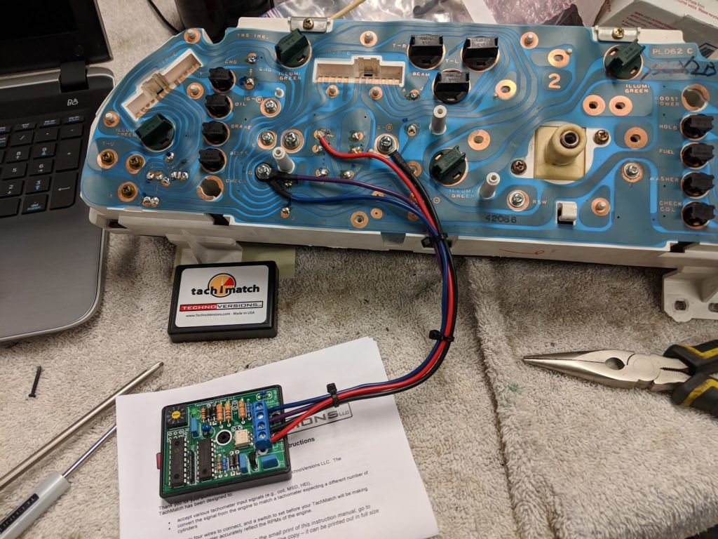
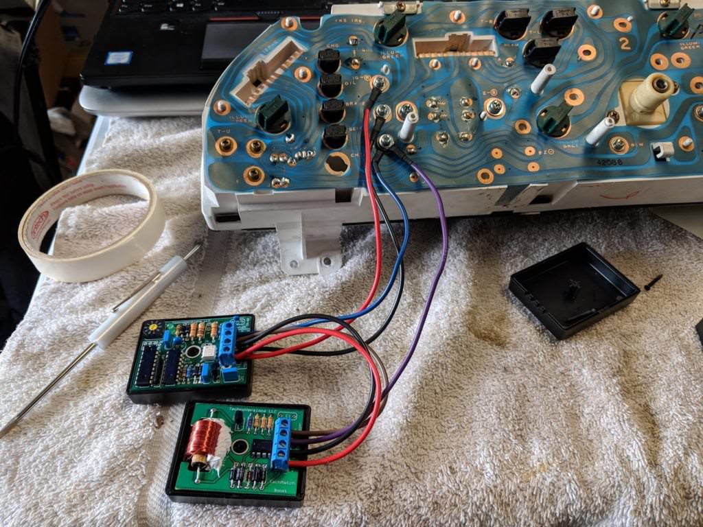
Now that the engine was fired up, it was time to take care of some of the
little things. One of these was the tachometer. As you remember, the stock
cluster was for a 4 cyl tach. I did not want to swap to the MX-3 cluster, it
would not have fit well and I also was not a fan of its appearance.
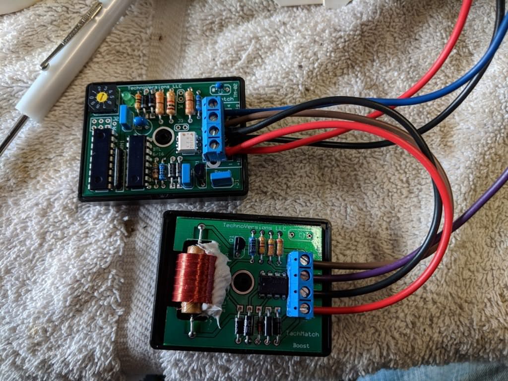
There are a lot of different tach converters on the market, but I decided to
go with TachMatch
([url]https://www.technoversions.com/TachMatchHome.html[/url]). It was
adjustable to fit your conversion ratio, had a nicely laid out PCB and
looked well made. It was also one of the cheaper ones. I wired it up,
intercepting the signal from the coil to the tach.
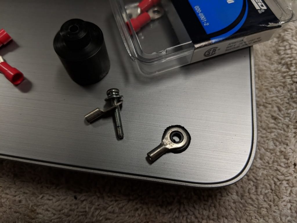
To intercept the signal, I made a little insulator out of delrin and used a
couple ring terminals. This way one ring can touch the flex circuit board,
and one can touch the screw, which goes through to the tach itself.
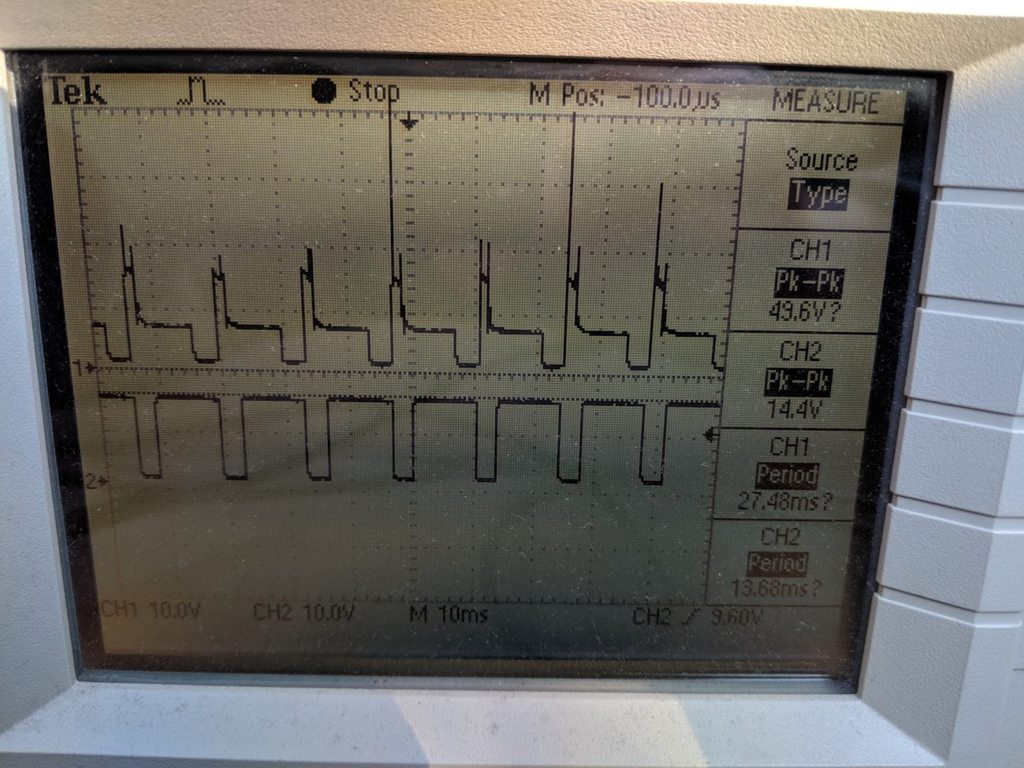
I eagerly turned on the car to try it out. Nothing. Boo. Time to toss an
oscilliscope on the signals:
Engine was idling (probably high), TachMatch in 1:1 mode. Top waveform is
the trigger input, bottom waveform is the TachMatch output. 10V per
division, 10ms.
I suspect that the voltage may not be high enough to drive the tach. You can
see from the bottom trace that the TachMatch outputs a nice square 12V
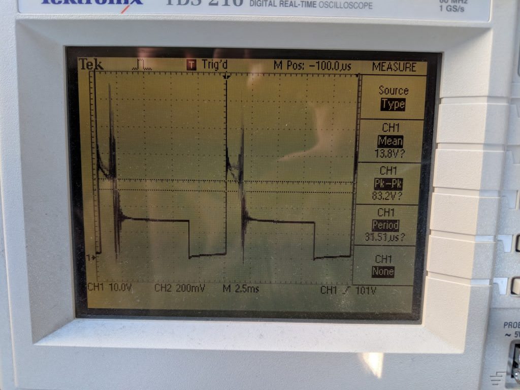
signal. The top trace is the stock tach signal, which has a high voltage
inductive spike. This spike is required to drive the stock Mazda tach.
You can see the voltage spike is quite high, 80+ volts for what the scope
can actually capture.
Luckily, the company also makes a voltage boost module. It creates the
inductive voltage spike required for the Mazda tach.
I added some electronics grade silastic to the inductor to prevent
mechanical vibrational stress on the leads. It's a heavy component, only
supported via axial leads so adding some mechanical fastening is important.
I also sprayed a silicone conformal coating on both boards, to prevent
corrosion.
After wiring it into the cluster, I now had a functioning and accurate
factory tach!
At this point, the engine is up and running and the cluster is reading
everything correctly without any check engine lights.
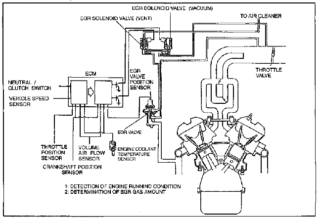
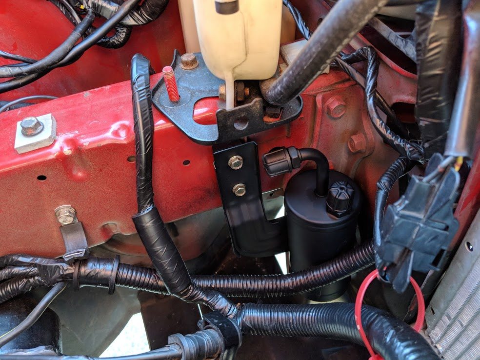
I had to do a bit of trickery for the EGR system. The KLZE engine does not
have any EGR, but the North American ECU's expect it.
There are two vacuum solenoids which control the valve, along with a
positional feedback from the valve itself. If the ECU does not see the valve
move correctly, it will throw an error.
The KLZE block has the mounting holes for the EGR valve, but no passages are
drilled. I decided to mount the MX-3 K8 EGR valve to the block and just cap
off the exhaust inlet. I also mounted the two vacuum solenoids and connected
them up as they would normally be. This would allow the ECU to see the valve
move, but not actually have any exhaust gasses pass. I was worried that a
lack of exhaust pressure would affect how the valve moved, but it seems to
have worked.
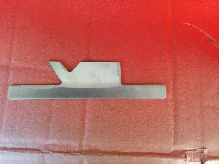
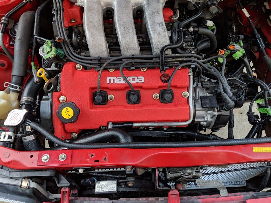
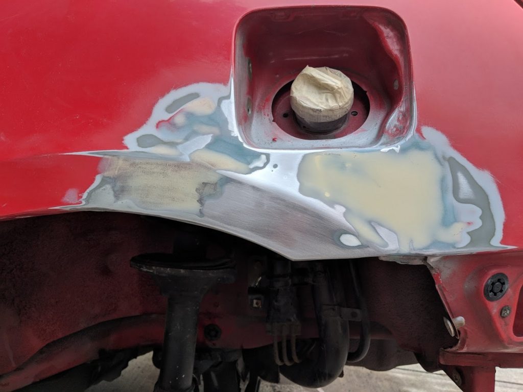
With that taken care of, it was on to the next important part. During my
refinishing of the intake manifold (who am I kidding, during it sitting for
years in a field), the V6 logo was destroyed. This left a weird outline cast
into the manifold.
Since I was not able to get a replacement, I had to make one. I cut out a
new badge from some stainless steel sheet.
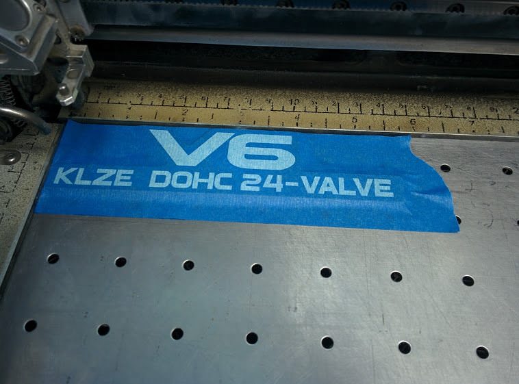
I then visited a friend with a laser etcher. We made a design and tested it
on some tape first.
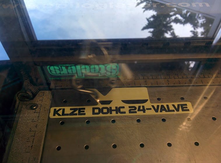
Then, after smearing the stainless with some etching compound we had this:
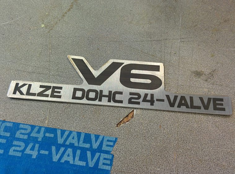
Some ultrathin high heat double sided tape and clearcoat and we were left
with this:
Much better!
I've been driving the car for a while and it's been performing really
well. It's quickly becoming one of my favorite cars to drive. While the 335i
is stupid fast, this car is quick. Acceleration comes right off the line,
unlike the 335 which has to build. Steering is quick and responsive, like a
go cart. The quicker ratio rack from the MX-3 GS means that occasionally
I'll take a spirited turn and find myself turning much quicker than I
expected. Almost like a forklift or something, it seems to pivot. I wonder
if the MX-3 rear steer suspension also has something to do with that.
The engine does like to be wound out, its got a good power band up into the
6k range. The VRIS comes into play around 4000 rpm, which ends up burying
the needle past 6500 very quickly. There is enough torque that second gear
starts are possible, though I feel it may be a little aggressive. You do
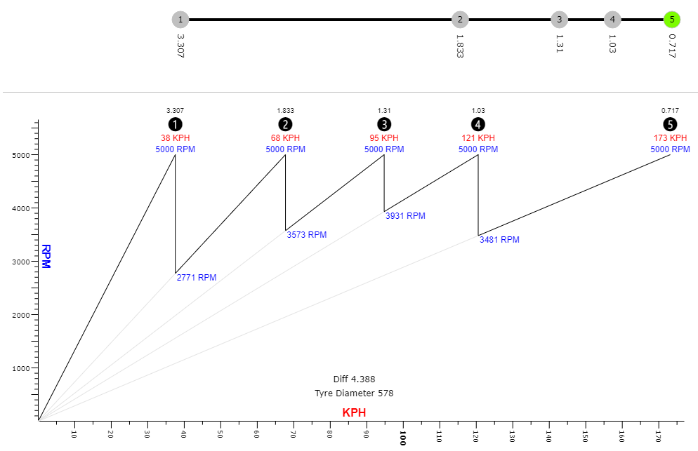
find yourself running through the gears very quickly. Driving around town,
60 km/h is a bit over 3000 rpm, so I've been cruising around in fourth. On
the highway, 90 km/h ends up in the 3200 rpm range, with 110 km/h at around
3600 rpm. This seemed a bit higher than I'd like, if only for fuel
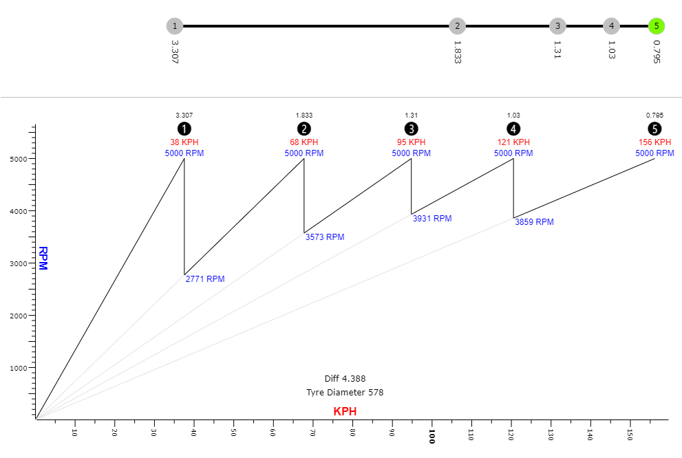
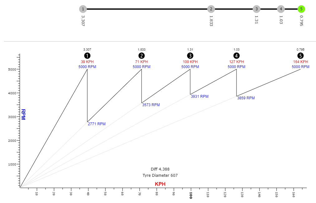
consumption. The tires from the 323 technically are ~3% smaller than an
MX-3, so I could probably get a bit better gearing by changing tires. I've
found that fourth gear seems to be nice to drive around town in, but that I
run out of gears on the highway. I did some reading and learned that the
fifth gear in a 87-92 Mazda 626 is a taller ratio.
So, a bit better, but tires are not in the cards currently.
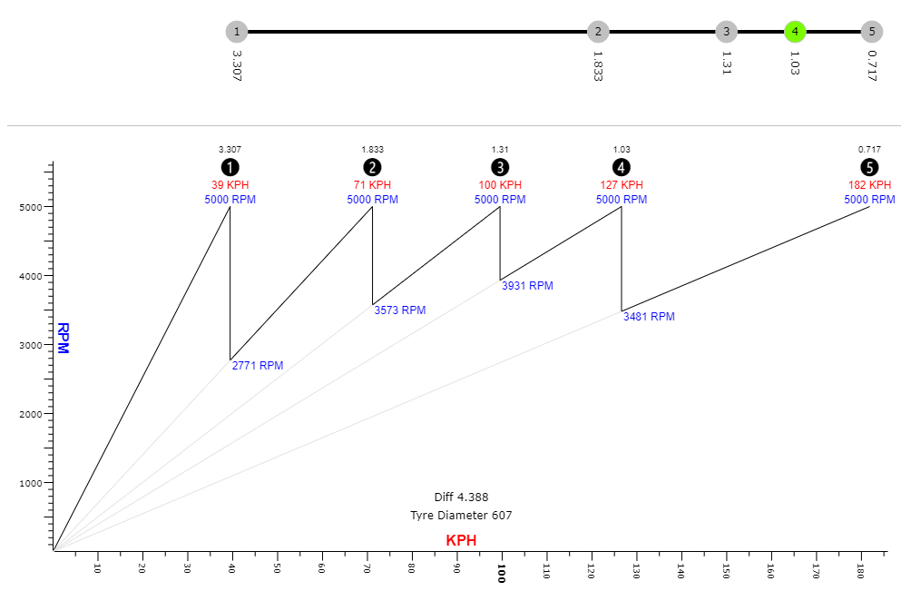
5th from the F series 626 (G25M-R) is 0.717:1. This should be a decent
reduction in rpm. Ideally, I would also want to change the final drive ratio
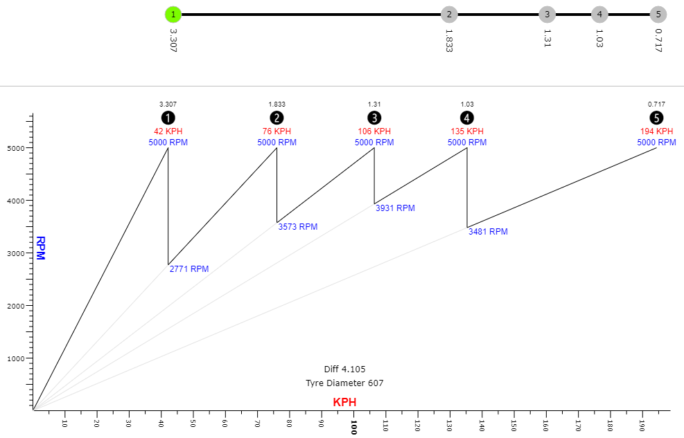
to that of a later KL-DE engined MX-6 or 626. They used a 4.105:1.
Eventually, I would like to use the Mazdaspeed Protege LSD, which also has
the 4.105:1 ratio. This would also probably significantly help with my
traction issues. Did I mention I have traction issues? I have to be careful
and try not to squeel the tires during spirited shifts. Yes, I can hold the
smoke through into fifth gear :D
323 tires and F series fifth:
MX-3 tires and F series fifth:
MX-3 tires, F series fifth and LSD:
So, ultimately, I want to get to the end case, but that will be a bit later.
Second gear on that transmission is a bit hard to select for the first
couple shifts in the morning when the transmission is cold, so perhaps
syncros are in need of attention.
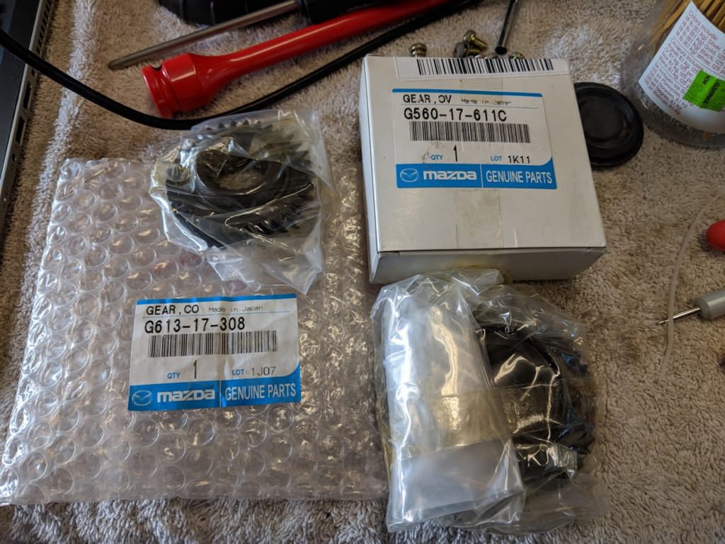
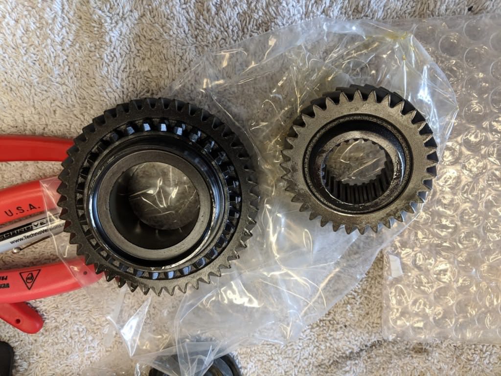
So, since there was no chance of finding an older 626 or MX-6 in the local
yards, I called up Mazda. $150 later I had G613-17-308 and G560-17-611C.
They were confused why I would be buying gears.
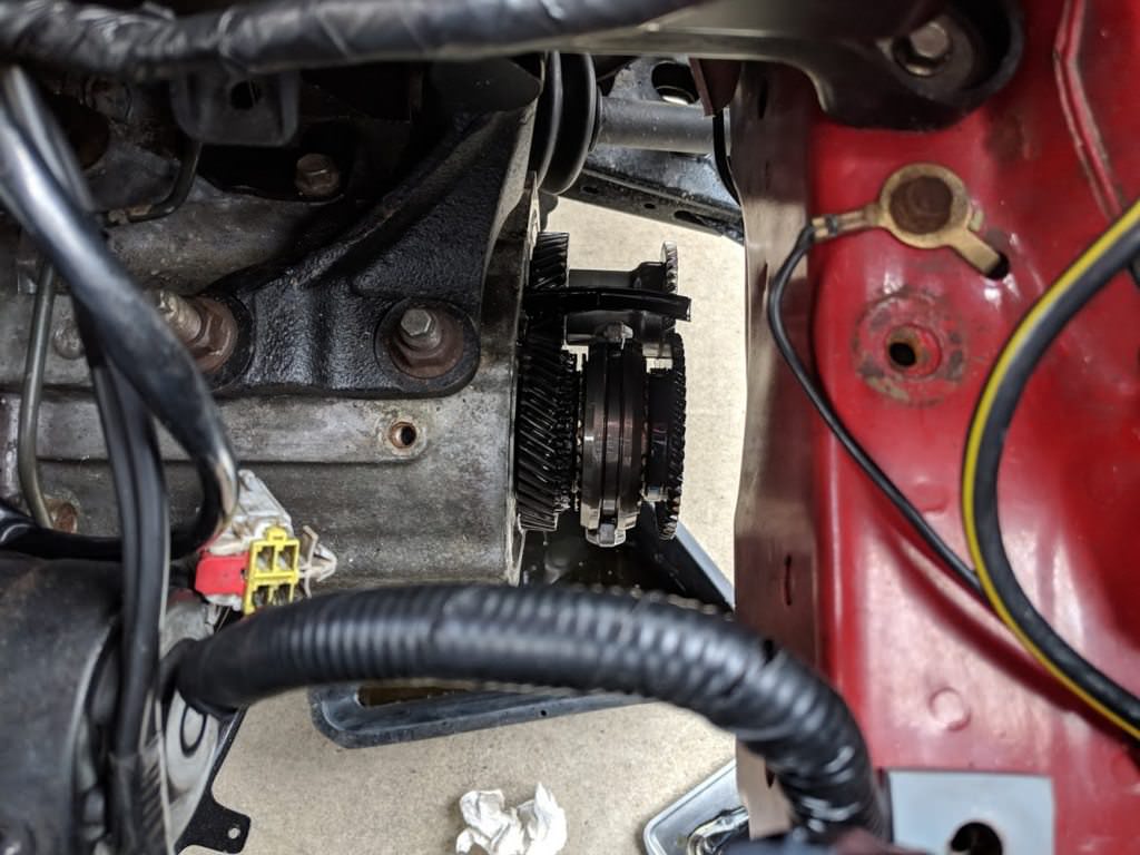
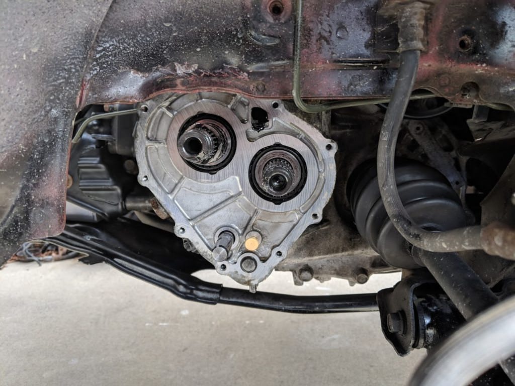
Luckily, I can swap the gears out, with the transmission in the car. It
looks like the G5 transmission was originally designed as a four speed, but
then they extended the shafts, slapped on a fifth gear and stamped out a
cover for the whole works. The entire fifth gear lives under that black
cover.
Cover off:
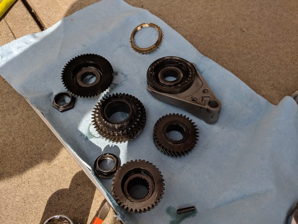
(Excuse the pinch weld bending. I bent it back after.)
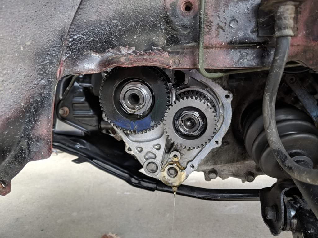
Gears removed:
The new gears:
I buttoned everything back up and topped up the transmission. I only lost a
small amount of fluid, as I was able to stick a golf tee in the passage
between the main case and the fifth gear cavity while I was working on it.
Highway driving was much improved, now I cruise in the 2400 rpm range. Fuel
economy is also better, though the car gets between 24 and 26 mpg.
No, no forced induction is planned. 10:1 compression makes that
difficult. Let's be honest, I have too little traction for the amount of
power already.
My hint was that given summer was approaching, it was starting to get hot.
Which meant driving around in a red glass greenhouse was pretty
uncomfortable. In the past, I had used this more as a winter car, as it
wasn't much fun in summer traffic jams. Time to change that.
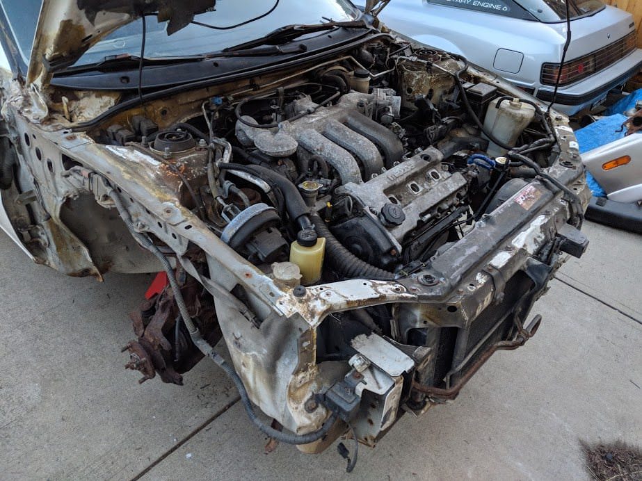
I'd always wanted A/C, but up in Canada, especially on the west coast,
finding one with A/C is near impossible. I would also need to figure out
some hybrid system, as I would need the compressor setup from a V6 to mate
up to the body setup of a 323. The 323 systems were mostly all R12, and
shared a lot of the same part numbers with the early MX-3 cars as well. I
figured if I could find an MX-3 system, I might be able to swap it in.
I'd been watching the local classified boards for a couple months, looking
for someone selling a car with A/C. I figured I would rob the A/C system and
then resell it, maybe taking a slight loss. Nothing ever came up. I branched
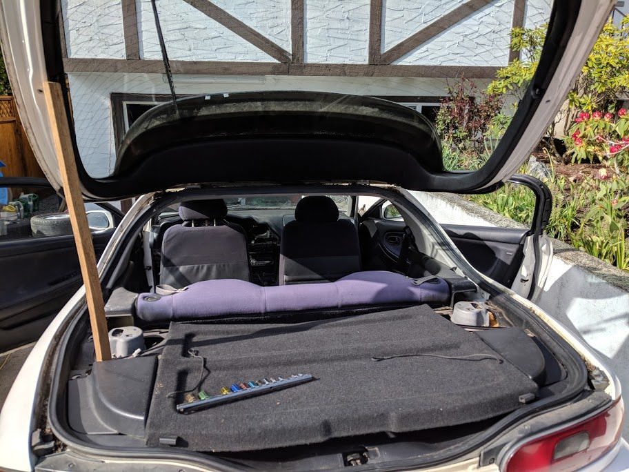
out my search province wide and found someone trying to sell a 1995 MX-3 GS
V6 for parts. Not running, had severe rust issues (push your finger through
the strut towers) and someone had ripped the brakes off it (I later found
them all in the trunk). Looking at the pictures, I could just make out the
AC hardlines. Great! There was just one small problem. The car was four
hours away, on the mainland. I was able to work out a deal, borrow my
friends truck (the enabler) and go snag it, for $400. It was actually one of
the better adventures I had, as we don't have very good junkyards on the
island and not only did I get the car, but I was able to stuff it full of
other parts from some wreckers over there.
Being a 1995 car, Mazda had switched over to R-134a at this point. The
entire HVAC system was also electronic and was a shot in the dark as to how
well it would transfer over. It did have the correct compressor mounts, as
well as a bunch of no longer available hardlines. It would still be a
mystery how well it would fit, as the MX-3 is about 6-8" longer in the
front, and the hardlines reflect this.
So, this will be the third MX-3 which will be sacrificed for this project.
I'm starting to feel a bit bad.
So, with the new donor safely at home, it was time to start stripping it
for parts. I genuinely felt bad starting this process, as the car didn't
look too bad at first. I mean, how many of these poor MX-3 have to be
sacrificed by my hands? I honestly thought about tossing the 1.6L B series
motor I removed from the 323 into it, but it was too rusty.
Before I could disassemble the car though, I had to unload it of all the
spares I had acquired on the way to pick it up:
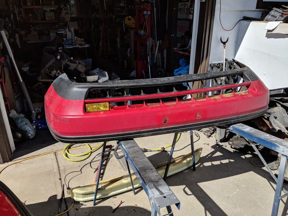
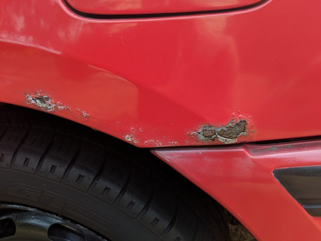
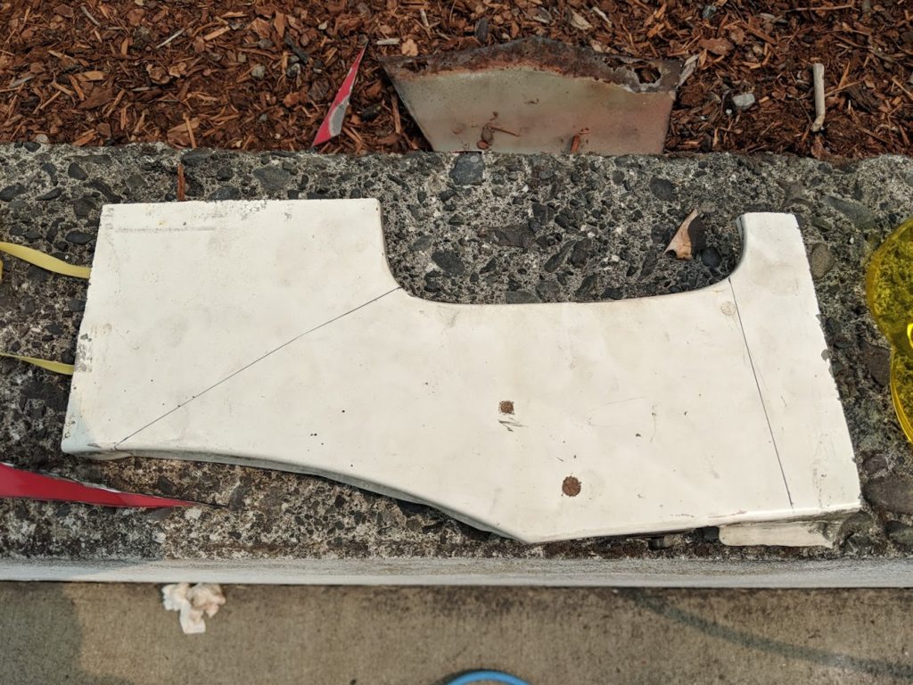
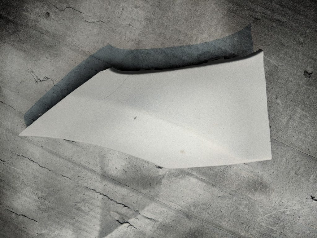
Some spare bumpers, lights and whatnot for the 323. Someone had repainted
the bumpers on the car years ago and the paint was bubbling and peeling off.
These would be easier to refinish.
Surprisingly, the MX-3 was fairly complete. It came stuffed with a few
spares as well, including a full set of new brake calipers.
Once I had the wheels off though, things took an ugly turn. I quickly
realized why someone had bought all new brakes and never installed them.
I could push my finger through the strut towers. Luckily, I don't need any
suspension off this thing.
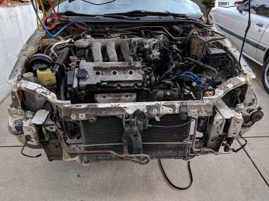
The engine bay was covered in this weird algae stuff. The AC parts I would
be using were all aluminum, so they should polish up okay. You can see one
in the picture here.
It was around this time that I started feeling a bit dumb for paying $400CAD
for this heap. I had to keep telling myself that it would be worth it for
the NLA hardlines, wiring, compressor brackets and HVAC boxes.
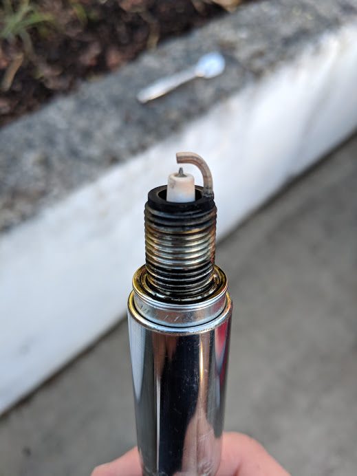
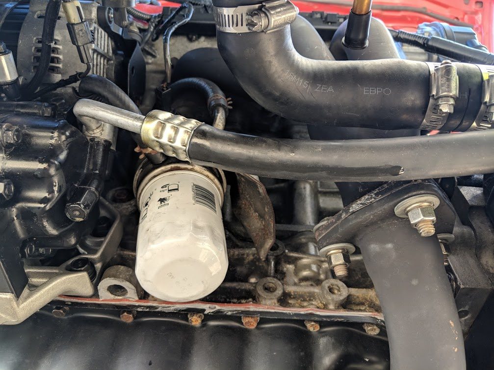
1000km have passed since I started up the KLZE for the first time. Decided
it was time for its first oil change and service. Figured I would check the
plugs to see how the ECU was running (the wideband had been showing the car
was pretty much always running in closed loop, even when you romped on it,
the ecu was fast enough to follow)
Plugs were all consistent and looked reasonable:
Around this time, a guy back east asked if I would fix up some of his ecus
for the KLZE. He shipped four to me, I fixed two and kept two as payment. I
tested them all, and now have been able to modify a KL48/KL55, two KL57, a
KL01 and a KL07. The KL01 and KL07 are the best candidates for modification,
as all their maps match perfectly in size. I never heard back from him after
sending them back, odd but hopefully they worked out for him. Seemed a bit
rude.
I commenced stripping on the MX-3. The thing really was just gross. Even
after vacuuming out all the tree bits, there sludge over the entire engine
bay.
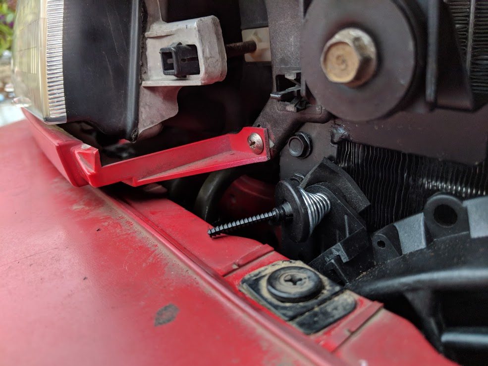
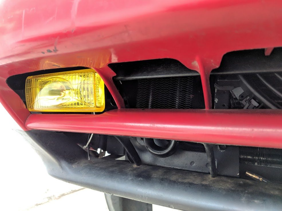
Hiding behind the front bumper was the condenser. I would need a new one as
this was very corroded. I knew this anyway, as I planned to get a new
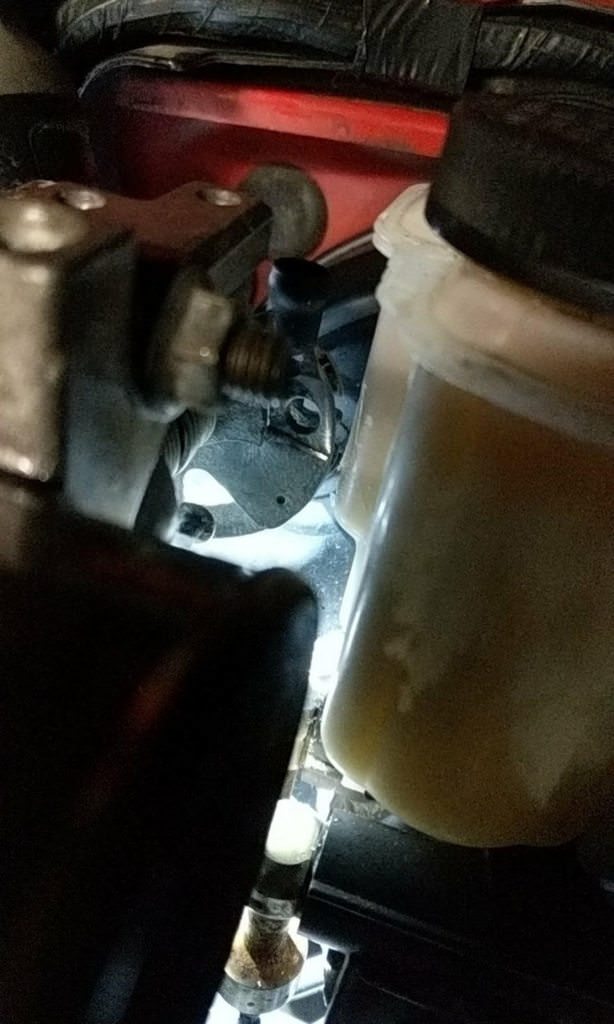
compressor, drier, condenser and expansion valve from the start. The system
still had some pressure though, and held vacuum perfectly, so at least it
was untouched.
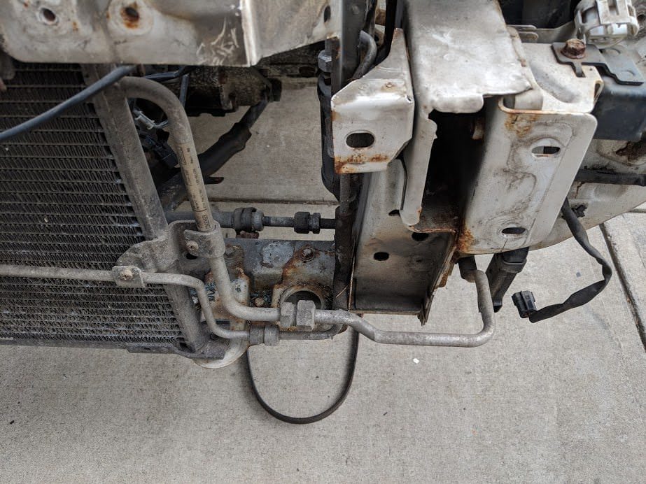
Crusty fittings, I guess the salt from the mountain town where this car came
from had not played well with the aluminum over the years.
They did come apart with a little heat, but instead of unscrewing, the
aluminum threads just kind of tore off on these two hardline sections.
Luckily, the fittings were only damaged between these lines and the
condenser, the threads between the body hardlines and these were fine. I
would need to get some lines made up to connect the new condenser to the
drier and compressor body lines instead. I was really upset at first that
these lines were damaged, but as the MX-3 mounts the condenser 6" further
out from the 323, these hardlines were too long anyway. The frame rails from
about 10" forward of the strut towers are different as well, so while I
could use the hardlines from the towers back, the part going to the
condenser would not fit in anyway. Flexible hoses will work much better, and
will follow the frame passthrough cuts which were already there for the
factory 323 system. I also learned that RockAuto sells crimp on metric AC
fittings, but doesn't list them in their universal parts. You have to find
the part number on the 4 Seasons website and then search RockAuto by part
number.
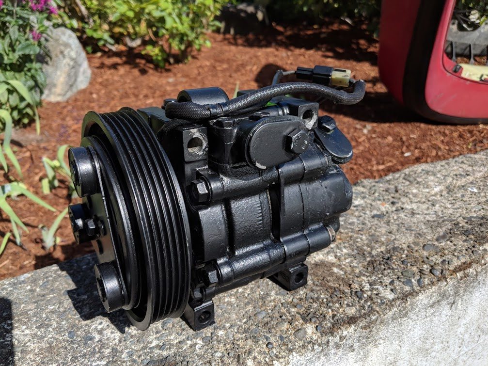
The compressor was equally disgusting:
It is probably rebuildable, so while I will buy a reman for now, I'll save
it for the future.
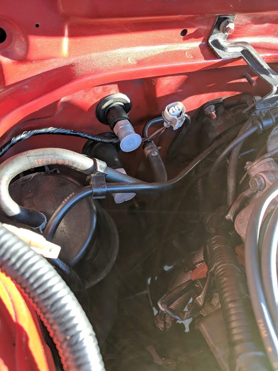
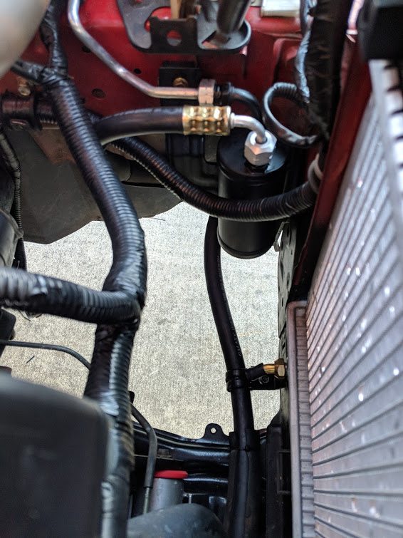
Receiver drier. One of the damaged hard lines connected directly to the
drier. The hardlines from the firewall to the drier came apart fine, and
would fit the 323 chassis.
Routing of hardline back to the firewall.
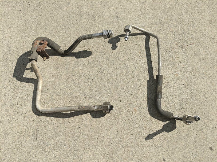
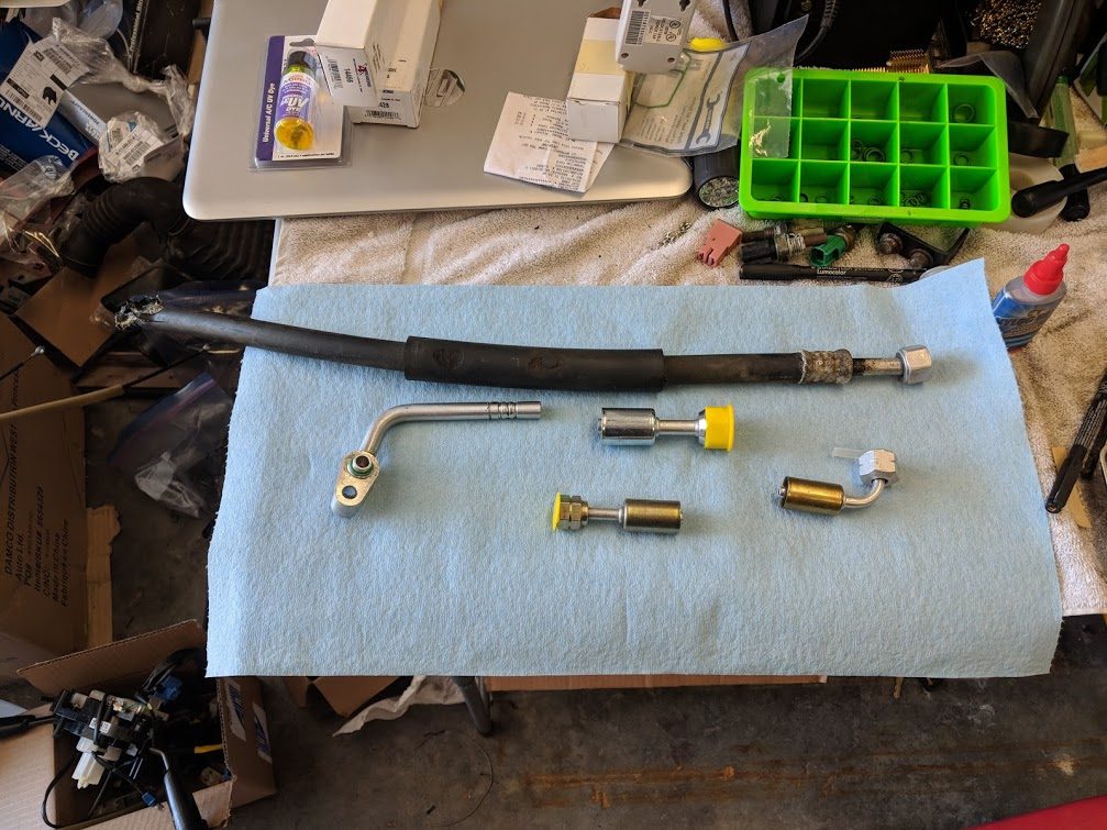
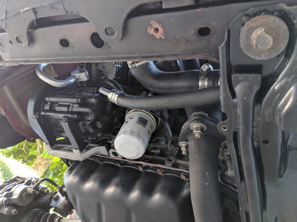
The other damaged hardline, connecting to the compressor hose. I will just
cut the ferrel off the compressor fitting, and replace the hose and hardline
with a continuous hose to the condenser.
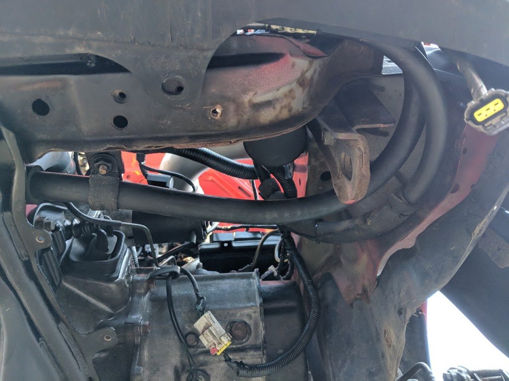
Suction hose from the compressor to the firewall. This would be reusable as
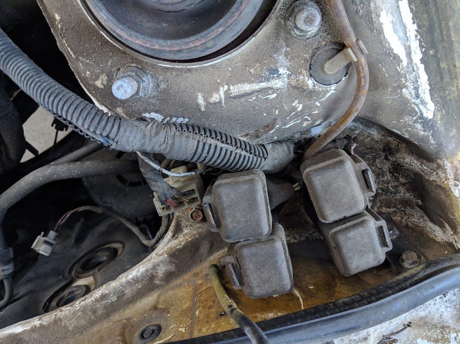
well.
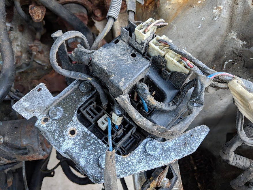
Four relays for the AC fan setup:
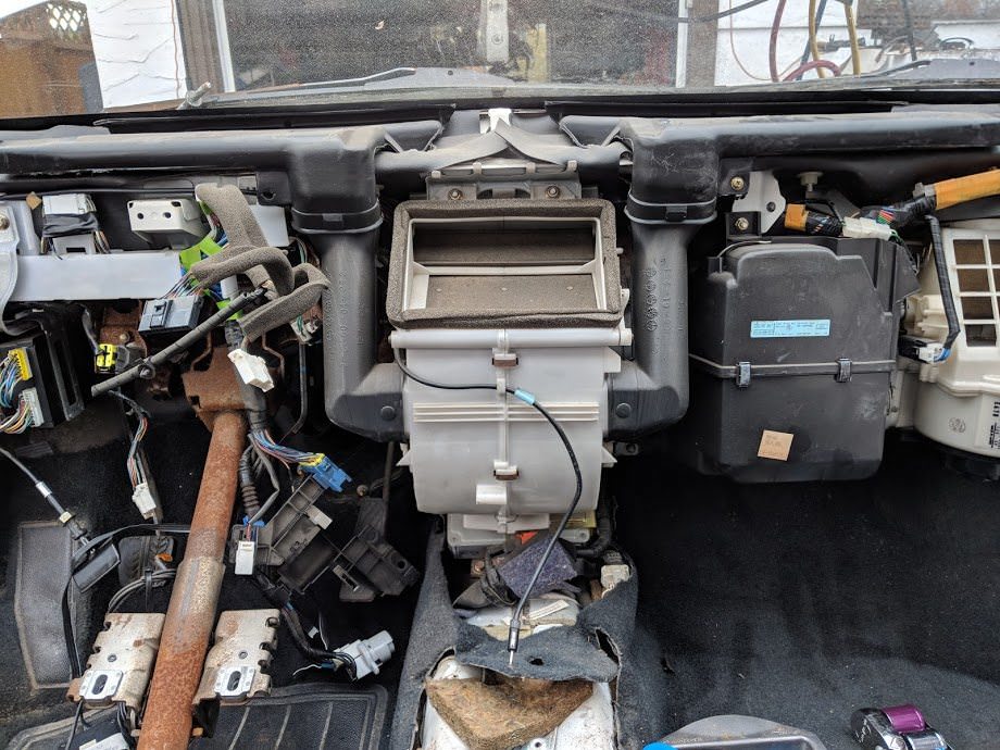
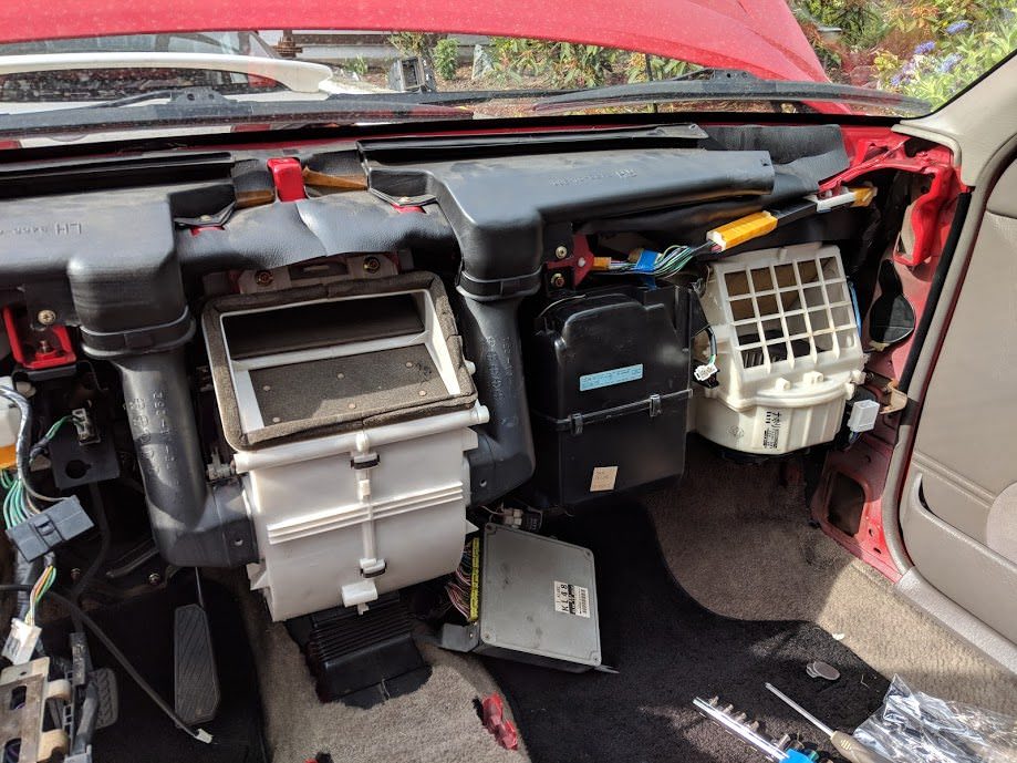
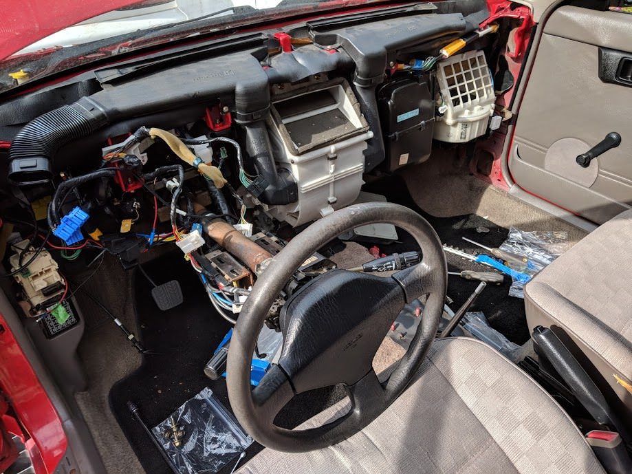
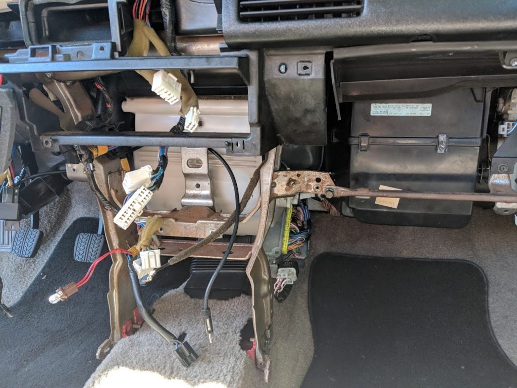
I also tore the dash out. The Mazda EPC showed different part numbers for
everything under the dash on the 94+, including the evaporator box. Of
course, they used the same parts diagram, but just changed the part numbers.
I knew the heater and blower box would be different, as they switched from a
cable actuated system to an electric one. There are no actuators on the
evaporator box, so I would have assumed that to have the same part numbers.
Oddly enough the pre-94 MX-3 used the same part numbers as the 323s (B
prefix), but the later ones got their own EA prefix part numbers instead. I
was hoping it would all fit, as no one has ever mentioned they tried
swapping them. Since the later MX-3 got R-134a, I think they updated the
part numbers at that time.
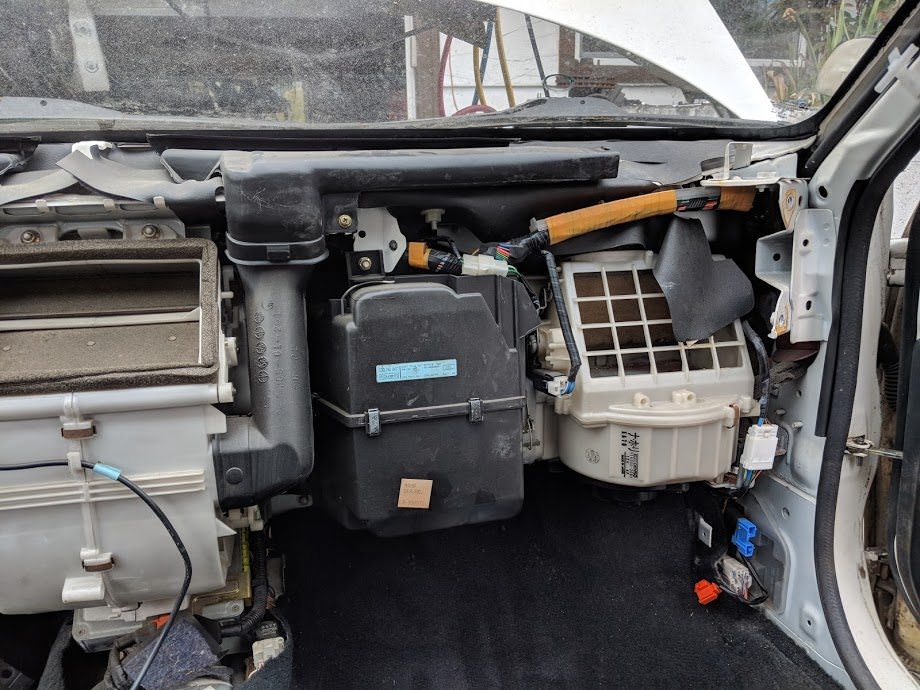
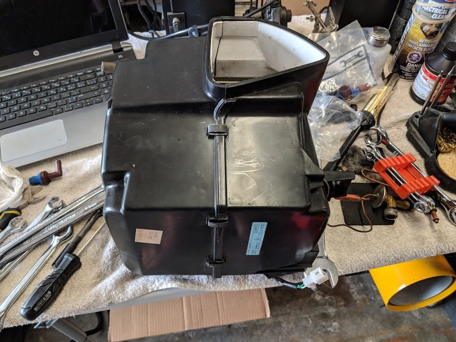
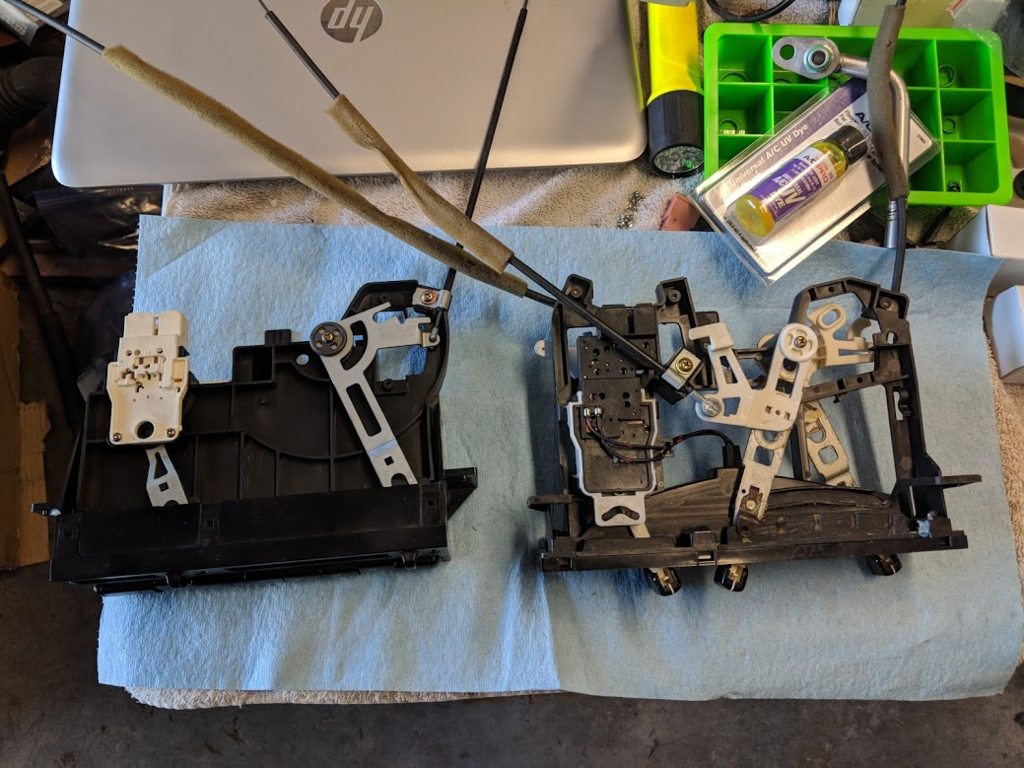
Heater box. This unit was white plastic, but appeared to have the same
external dimensions and fittings of the earlier MX-3 and 323 boxes. The
323/MX-3 cable actuated boxes have all been made from black plastic. You can
see the evaporator box to the right.
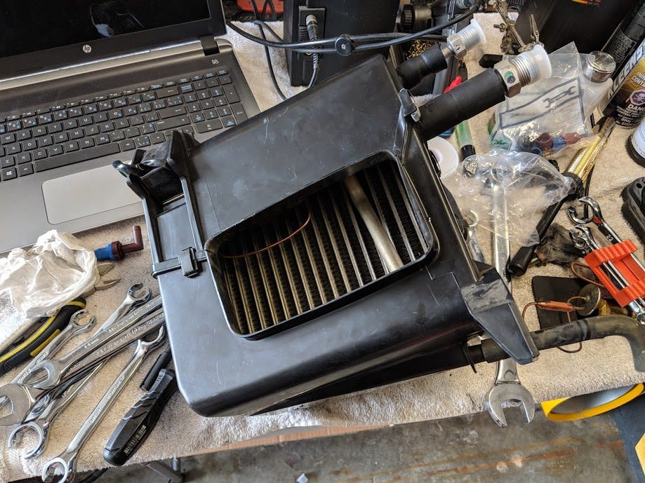
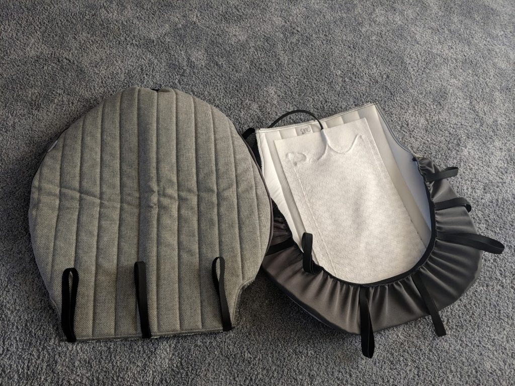
Evaporator box and blower motor. Again, the electronic actuated box is white
for some reason.
In a non-ac car, the evaporator box is replaced by a simple duct to connect
the blower to the heater box. The AC stuff interestingly was all tagged as
made in the USA. The fasteners used were also slightly different, smaller
flange nuts were used for example. I wonder if these were ever dealer
installed.
Now that I had all the AC parts removed, it was time to clean them up and
see what condition everything was in.
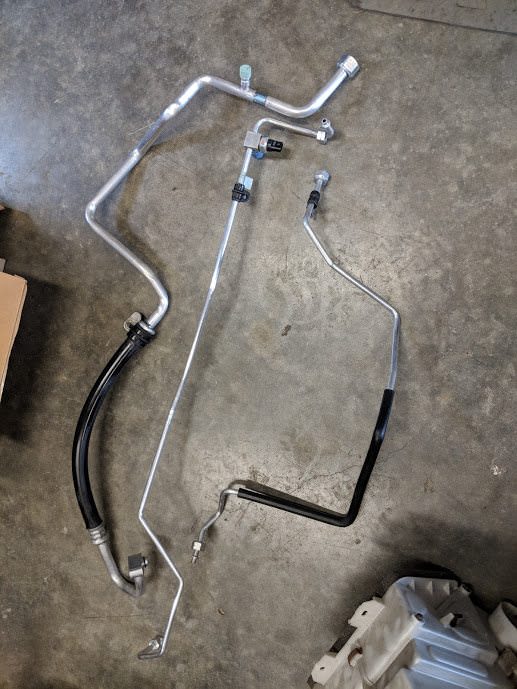
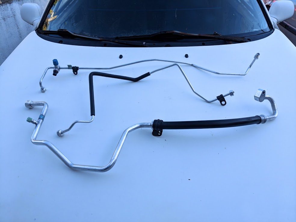
First up was the AC hardlines. A reminder of what condition they were in:
Those were the two damaged lines, but everything was in similar condition;
corroded and covered in a mildew of some sort. After a lot of scrubbing with
scotchbite and some solvent, I was left with these:
Honestly, they came out great. The factory part number tags cleaned up as
well, I decided to leave them on for a factory look.
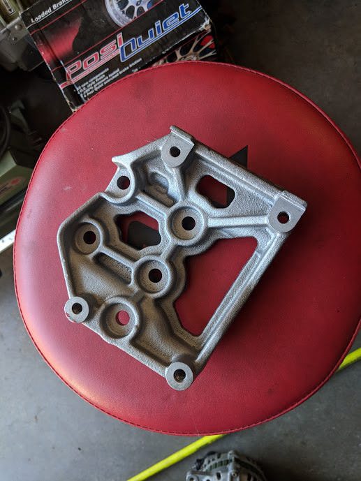
The crusty compressor mount was glass beaded and clearcoated:
Painted the mounting bolts as well, and fit it up to see how it would work.
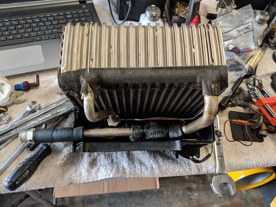
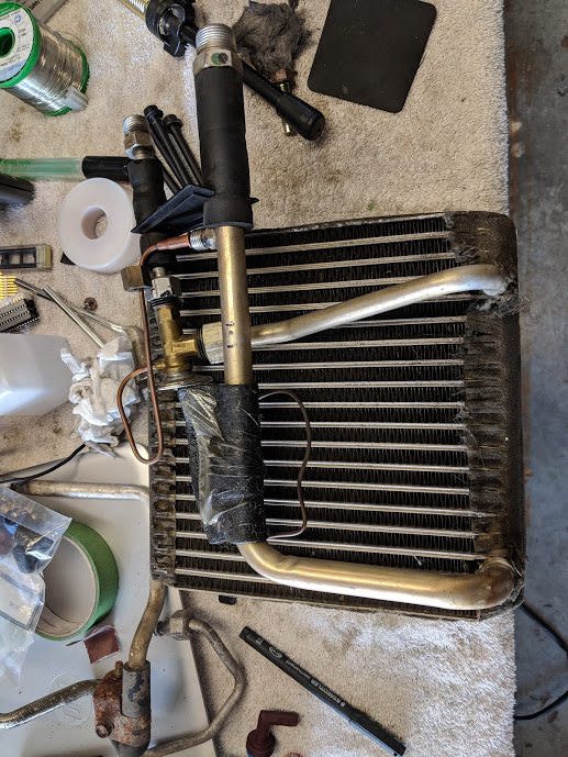
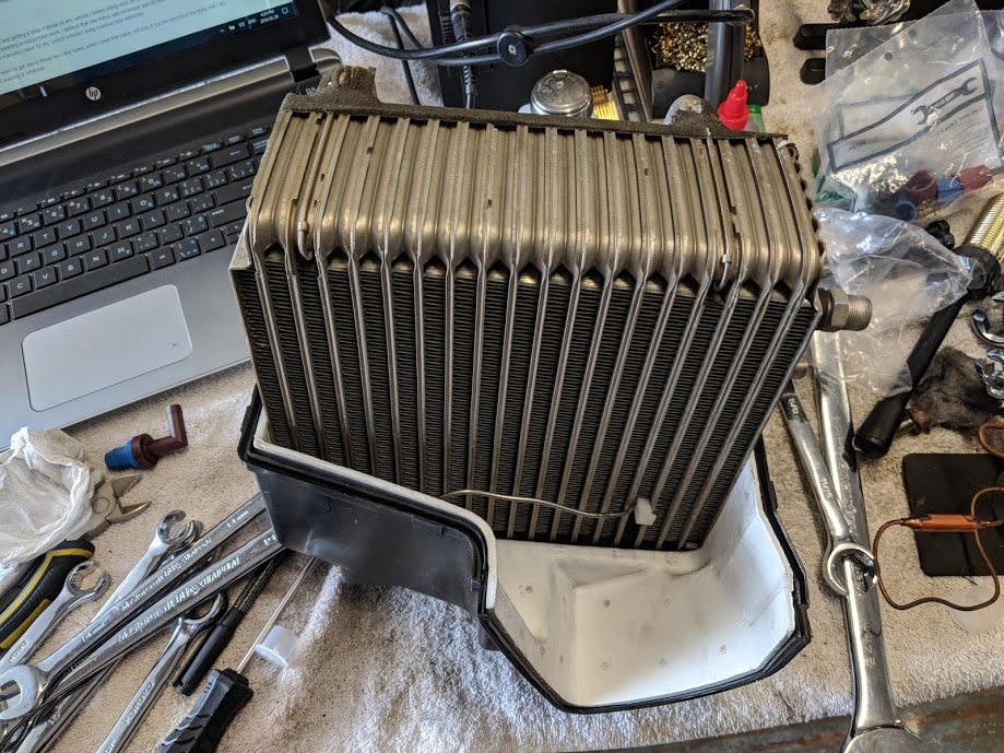
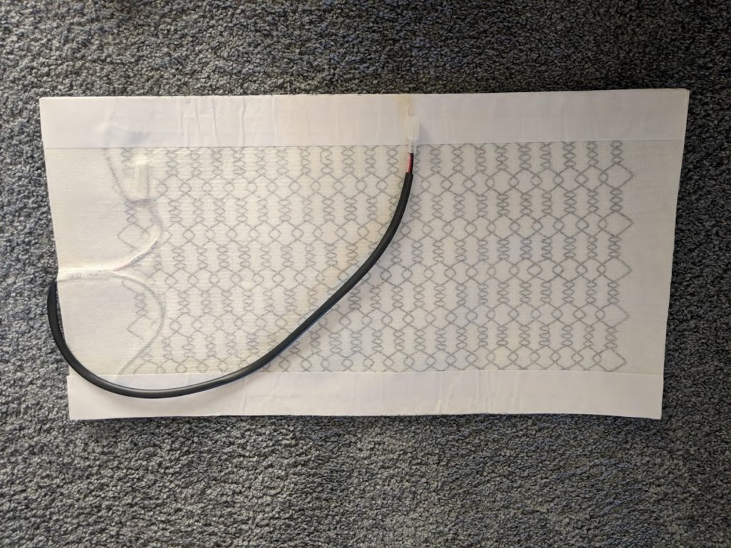
Next up was the evaporator core. Since it was out, I decided to replace the
expansion valve. The core itself looked in good shape. They seem to build
them well. Some minor dust and organic matter was removed from the fins.
Fitted back into the box.
Painted the clips for the box and reassembled.
Cleaned up the blower motor box as well. I had to swap the flapper doors
from the old 323 box, as the foam on the MX-3 one was destroyed. After
regreasing all the pivot points, it looked great.
I also swapped the 323 heater core into the MX-3 electric heater box. The
main difference is that the 323 outlet/inlet are straight, whereas the MX-3
has a 45 degree output angle.
Now for the moment of truth. Would the electronic boxes fit in the 323
chassis?
Yes they did. This is now the third time I've taken the dash out.
Having confirmed the HVAC boxes from the late generation MX-3 would fit in my chassis, I could proceed with making permanent modifications to get the rest of the car to fit. The new boxes were all electronically controlled, so after studying the electrical wiring diagrams, I decided it would be easiest to remove the AC and HVAC wires from the MX-3 harness and splice and wrap them up in my already modified V6 323 harness.
Out came the gloves and scalpel, and I started the wonderfully sticky task of unwrapping yet another wiring harness.
I got lucky on some of the AC portion of the harness. It was done as a separate add-on from the factory, which meant it just plugged into unused ports on the fuse box:
The 323 fuse box has some different connections, but they could still be adapted to work. At the same time, I added a couple more circuits to the underhood and cabin fuse boxes, one for fog lights and another for other accessories down the road.
I also discovered the MX-3 had factory electric door locks. There is a switch on the driver's lock which provides a signal to an actuator on the passenger door. The system is simple; the passenger door lock basically follows whatever state the driver's door is in. No lock or unlock switches. Now, the 323 locks were similar, but lacked the mounting locations for the switch and actuator. I drilled out the spot welds and rivets on the lock mechanisms, and welded them back together so the 323 could accept the MX-3 wiring. Sadly, I never took any pictures, but it took me a few hours to work it all out. Perhaps one of the more tricky parts of this build so far.
I had also noticed an oil leak since I had been driving the car more. Both valve cover gaskets were weeping significantly. I had used some cheap ITM branded gaskets and after some googling, I learned these engines like to leak. I ordered some Mahle gaskets, which were made in Japan and some ultra grey gasket making RTV and got to work taking the intake off again.
It turns out that in the MX-3 manual, for the K8 engine, it states to use no sealant, but in the MX-6 manual, for the KLDE, they suggest a light coat of RTV. The MX-6 manual came out later, so Mazda must have had problems with leaks themselves. It was actually helpful to take the intake off, as it gave me more room to work on the AC piping.
Next, it was time to come up with some sort of mount for my condenser. The stock 323 condenser mounted between the headlights, in front of the radiator, in the location I had mounted my radiator. I would need to push my condenser further forward, and trim the grill to give me more room.
A reminder of how much room I have:
Not much. Oh well, I will mount the condenser as close to the radiator as possible and then go from there.
I cut off the MX-3 condensor mounts from the MX-3 chassis and got to work welding them up to the 323 crossmember.
A little bit of paint later:
This allowed me to retain the rubber isolator feet from the MX-3 condenser. I was also able to modify the upper mounts to fit with my custom radiator supports.
Quickly put together to see how it would fit:
I had to trim a bit of the plastic behind the grill, but it doesn't change the look at all. It should work quite well. Next up, cooling fans and some other type of power steering cooler setup. The shape of the stock one fouls on the condenser.
Now that the condenser was mounted where it had to go, we had a couple issues.
- The power steering cooling loop was bent in such a way that it would not lay flat in front of the condenser. It was twisted backwards to fit into the front grill. If I moved it out further, the tube would foul on the bumper support bar.
- The hood latch support brace fouls on the condenser. It is removed in the earlier pictures, but is necessary to reinforce the latch from twisting down when the hood is shut. It is especially critical now that the rad support has been cut out.
- The Toyota electric fan no longer fits between the radiator and the crash bar. It also is probably inadequate due to the condenser increasing the heat load.
A clear shot of the interference on the power steering cooler. If I bend the cooler flat, there will still be no room for fans. For now, it will be removed while we mock up the fans.
I decided to use a pair of single speed 10" low profile fans. Cheap and readily available off Amazon (except in Canada, I picked these up from an Amazon locker in the USA on a work trip). Given my tight clearances, slim was very important.
I drilled some holes and bolted them together at the center to become one unit. I also applied stickbacked foam to any parts which would be in contact with the condenser.
I mounted them as a test fit:
Not so bad. I don't like the mounting hardware, for the final install I added zap ties as a stop to keep the round keepers on the long plastic pieces.
The fan motors fouled on the crash bar unfortunately. I could just get it to fit, but it put more pressure on the condenser than I was comfortable with. Instead, I would rather the condenser and fan assembly could float on their rubber isolators.
Out came the holesaw and die grinder:
I was really torn on cutting into this bar. I didn't want to reduce the structural integrity of the bar, but there was no other option.
Next, I had to get really creative with the hood latch. I used the top part of the 323 bar, the lower part of the MX-3 bar and then turned the middle part of the 323 bar inside out and welded them together with some stiffener pieces.
It looks absolutely bizarre.
But, it does fit!
It even clears the crash bar!
Next, it was time to turn my attention to the power steering cooler. The stock 323 and MX-3 used a loop of hardline in front of the radiator.
You can see the MX-3 shape here. It also isn't suitable.
There just wasn't enough room to fit it in between the bumper cover, the new electric fans and the new hood latch support.
I did however have a significant space beside the radiator, under the headlight which was free. I thought I would try to find a finned cooler, which would be smaller and fit in that space. Although my total system fluid volume would be reduced, I figured the increased surface area from the fins would make up for it. I took some measurements and got to google image search/rockauto random vehicle shopping.
After a few hours of searching, I found this guy, a Dorman 918319:
It was off a 1996-2014 Ford E-250 4.6L V8 van. Best part, it was readily available in town/Canada for $15. It would fit perfectly in the space beside the radiator, and the tubing diameter in the main portion with the fins was just a bit larger than the stock cooler. I didn't want to have any AN fittings to keep it looking stock, and the price of aftermarket coolers were high.
There was one problem however. The hoses on a Ford Econovan are imperial and significantly smaller than the stock Mazda lines. I didn't want to create a flow restriction, so I would need to cut off the existing Ford nips. Out came the hacksaw. I also turned some aluminum tube down in the lathe to a metric OD.
I used some Devcon aluminum epoxy to secure the fittings. I had thought about brazing them on, but the Devcon stuff was pretty decent. Its mostly powdered aluminum and cures to a machinable compound. [url]https://itwperformancepolymers.com/products/devcon/devcon-products/devcon-aluminum-putty-f[/url]
Next, I reformed the mounting ears to fit the 323 and gave it a coat of high temp paint:
Finally, I cut some of the old hardline cooler and used some extra hose from the MX-3 to connect it all up.
Just clears:
I wanted a set of yellow glass lights, but I wasn't a fan of the GTX grills which mount them between the headlights, as I don't exactly have a ton of room up there anymore. I decided to mount them on the crash bar, using some small ABS spacers. I then spent a couple hours trimming and sanding the bumper cover to allow the lights to clear.
I wanted to make sure they were tucked back, up and out of the way, and didn't look like they were stuck on there from the side. The bumper cover is pretty beat, but that's for later.
With the bumper covers back in place, it was time to replace the leaking valve covers and connect the ac hard lines in the engine bay. The factory service manual for the MX-3 with the K8 engine stated to install the cover gaskets without any extra sealant, but the MX-6/626 manual, with the KLDE engine stated to apply a thin coat of sealant to the entire gasket. I had originally followed the MX-3 manual, and given that the rear cover is canted backwards, oil is always against the seal. This lead to a leak, which in turn dripped over my exhaust. So, after buying some better Japanese made gaskets and some black extra oil resistant RTV, everything was back together leak free.
I still love looking at those valve covers.
A grouping of all the shiny, restored hard lines.
The AC evaporator core connections poking through the firewall:
The first hard line installed:
I was able to use one factory tapped hole for the drier, but needed to drill and add a rivnut for the other. The 323 chassis was never intended to have a drier here.
Hard line to drier installed:
Hard lines connected together. Luckily they cleared the air filter.
I considered rebuilding the existing compressor myself, but the cost of the rebuild kit was nearly the same as a reman compressor. Easier to get up in the great white north as well. Look at all that shiny black paint:
Its future home, with the newly refinished bracket installed:
Slotted in, nothing difficult here, but luckily it does clear the radiator:
Since I needed to swap the drive belt to a larger size anyway (anyone want a non AC KL belt, only 50km on it!) I decided to also rebuild the power steering pump. I had noticed a little bit of weeping along the pump body seal. As usual, the rebuild kit is another part local parts stores don't carry. I picked up a kit when I was down in the USA last.
Greasy pump:
Partially disassembled:
The bearing there was a bit ugly, so I also replaced it.
All the pieces and seals:
Glassbeaded, clearcoated and reassembled:
Onto the rubber bits! Since the AC system was designed for an MX-3, the condenser would have been mounted about 6 inches further forward. If you remember, the lines connecting to the condenser did not come apart and thus I needed new fittings. Given that the hardlines would not be correct anyway, I decided to abandon the short lines and use a rubber line instead, replacing the original rubber line to the compressor which was also attached to the damaged hardlines.
I was able to order three crimp on metric AC ends from rock auto's universal component section. I carefully cut the compressor fitting crimp sleeve off the original flex line and saved the fitting for reuse with a new crimp sleeve.
You can see the cut off hose on the top.
Next it was time to crimp on the new ends to new hoses. I started at the condenser.
The stock 323 AC system used a passthrough in the body to run its lines. I routed the hoses along the same path.
One hose up to the drier:
The other hose across the engine to the compressor:
Time to reattach the bumper and check clearances:
Looks good. The undertray will cover these and protect them as well.
Last, lets check if it holds vacuum:
Awesome.
Time to turn my attention to the HVAC controls.
I had gotten enough of the dash back in to have the stock wiring and the new harness for the electronic HVAC boxes. The dash has an internal frame to which the HVAC control unit and radio are mounted, and then trim pieces cover the rest.
Here is the manual 323 HVAC on the right, and the 95+ MX-3 HVAC module on the left. They are roughly the same height, but the MX-3 unit is about half an inch narrower. The mounts are in no way the same.
I ended up cutting off the mounts from the 323 unit and screwing them onto the MX-3 mounting ears. Luckily, they seemed to line up well for depth. As for the width, I cut up an old broken radio surround and glued them to the side of the MX-3 unit. Pay no attention to the chipped plastic, the trim covers that up.
Next, add the trim and radio, and its back together.
Nearly looks stock, doesn't it.
While I had the harness out again to splice in the AC harness, I decided to add a few other electric features.
Both the fuse box under the hood and the box in the footwell had some spare, unused fuses. I decided to use contacts stolen from a spare box to add a few more circuits.
First, the underhood box. I added a 10A fuse to supply the foglights. As well, I printed a label to match as best as possible.
I found a Miata fog light switch, which matched the 323 switch style perfectly.
I found a brown raised armrest from another MX-3 at a junkyard, and the later cupholder style 323 center console as well.
I liked the map lights the MX-3 used, so I retrofitted them into the 323 headliner.
The 323 never had passenger handles, just blanking plugs. I installed some from a couple MX-3's.
I also wired up the adjustable intermittent delay windshield wipers from the MX-3.
From a junkyard Protege I grabbed:
-Tilt adjustable steering column.
-Ignition key courtesy light.
-Windshield washer reservoir level sender (Since the new tach cluster had a light)
-Low fuel level sender (Since the new tach cluster had a light)
Additionally I added a couple diodes to the body junction box computer to enable the door ajar buzzer to beep when you removed the keys but left the lights on.
The dash looked completely stock
I added a 30A to the footwell box.
Yes, I had decided to add heated seats as well. I found a company on RockAuto (Dash Designs) who still made custom seatcovers for 323s. I also picked up a cheap heated seat kit from China. They consist of sticky heating pads, which you put under the upholstery. Since I was going with covers, I just stuck them to them.
The heating pad. You can cut them slightly, but I was able to fit the entire mats on both the seats and backs.
One pad installed.
Finally, I wanted to add homelink. I bought an Audi A4 visor off eBay, as they had a cover which concealed the entire homelink module. I carefully cut out a rectangle and installed in the the 323's visor. Interesting to note, the Audi had a 1x12" aluminum tape antenna, which was adhered to the plastic homelink body and then extended 10 inches off, through the rest of the visor. I had read other people complain that the modules do not have great range, but none of the modules on eBay seem to come with the antenna. I suspect noone who retrofits uses the antenna. I did, and my range is easily a couple hundred feet.
Now that most everything mechanical was complete, it was time to tackle the cosmetics.
Rust! No BG 323 would be complete without at least a light dusting of sockington's revenge. Luckily I had only a couple places on the entire body.
1. Underneath the roof body crease for the rear hatch. This was minor, just a light surface rust with no pitting or any holes. Just a simple sand, prep and paint was needed. (I used an etching primer, a sealer primer and a topcoat).
2. The rear driver wheel arch. There is a spot welded seam along the back side. I guess the seam sealer failed and the body started to rust from the inside out. It was starting to get quite bad.
As with any rust from a seam, what was showing was only the tip of the iceberg.
Sandblast to remove the rust and paint. It's amazing how many pinholes appear. It also amazes me how the sand literally gets everywhere.
I then marked out how much I was going to cut out. I figured it would be easiest to split the seam at the fuel door, as the outer skin was spot welded in two places here.
As I cut, I found the rust followed the seam further inside. I ended up needing to cut away this much until I had fresh steel.
Paint removed, prepped and sprayed with a weld through primer.
A few months earlier, I had cut out a patch panel from a junkyard car. The pick n pull was very confused when I asked for permission to do this, but as long as I wasn't using a grinder, they had no problem with it. Luckily, I had brought my M12 hackzall.
Mark out the patch.
Cut to fit and prepped with weld through primer as well.
Welded in. The zinc primer made it really hard to get a clean weld. It also really sucked to weld the inner wheel well portion.
Add some fancy filler.
Sand, add catalyzed glazing putty and repeat.
Then spray guide coat, which helps you see imperfections. Add more filler, sand, guide coat, sand, filler, guide coat, etc, etc, etc.
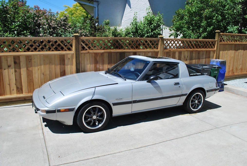
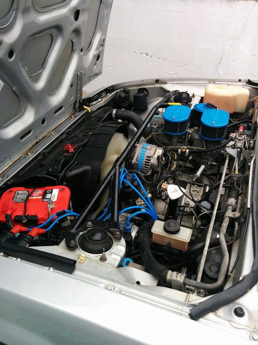
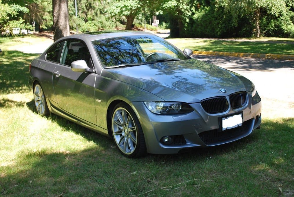
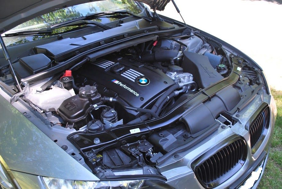
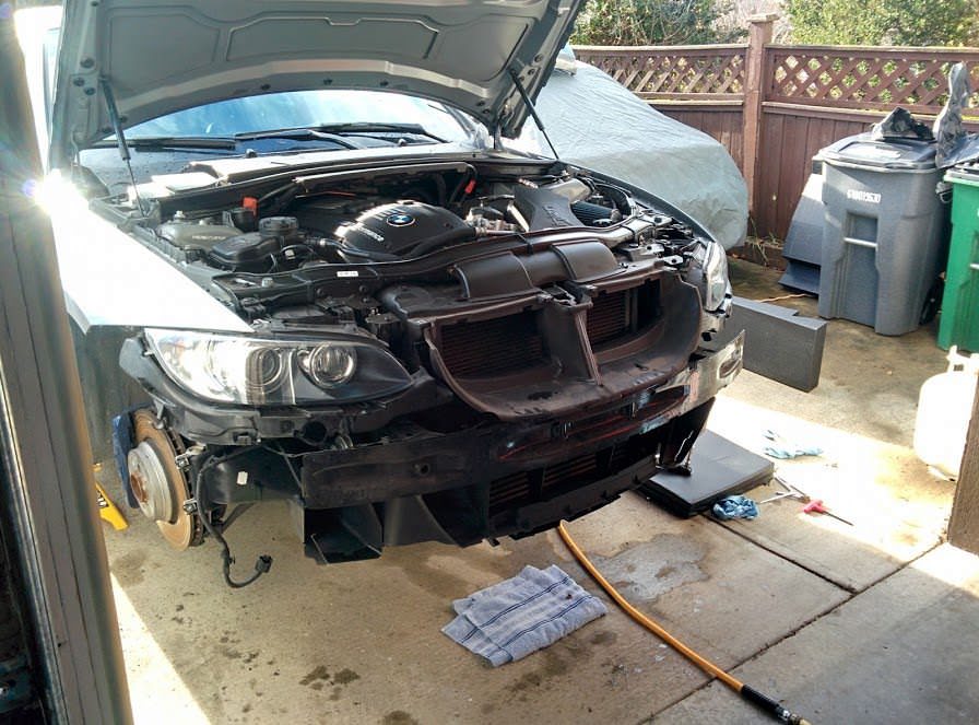
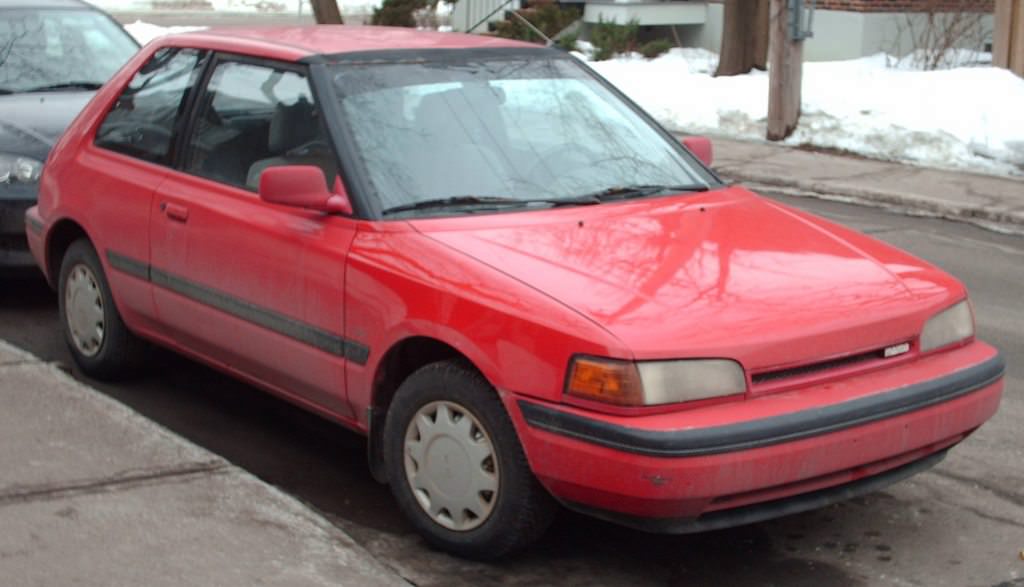 (I don't even have a picture, I'll take one tomorrow)