FUEL INJECTOR INSPECTION
BHE011413250W02
-
Warning
-
• Fuel can ignite and cause serious injury or death, and damage. To prevent this, always make sure to follow the warnings and cautions for each procedure when repairing or inspecting.
Fuel Injector Operation Inspection
Fuel injector (FP1, RP1) operation inspection
1. Warm up the engine and idle it.
2. Inspect the following PCM output wave pattern. (See PCM INSPECTION.)
-
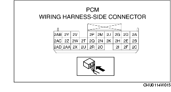
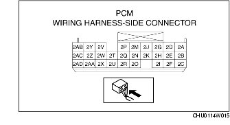
• PCM terminal 2M (FP1)
-
• PCM terminal 2J (RP1)
3. If a normal condition of the PCM wave pattern cannot be verified, inspect the following and repair or replace the malfunctioning part.
Fuel injector (FP1)
-
• Short circuit of the wiring harness, connector between fuel injector (FP1) terminal A and main relay terminal C

-
• Short circuit of the wiring harness between PCM terminal 2M and fuel injector (FP1) terminal B
-
• Short circuit of the fuel injector (FP1) internal circuit
Fuel injector (RP1)
-
• Short circuit of the wiring harness, connector between fuel injector (RP1) terminal A and main relay terminal C
-
• PCM terminal 2J-fuel injector (RP1) terminal B
-
• Short circuit of the fuel injector (RP1) internal circuit
Fuel injector (FP2, RP2) operation inspection
1. Connect the WDS or equivalent to the DLC-2.
2. Warm up the engine and idle it.
3. Monitor the following PID.
-
• Engine speed signal (RPM)
4. Verify that there is no output of the fuel injector (FP2, RP2) control signal wave pattern from the following PCM terminals. (See PCM INSPECTION.)
-
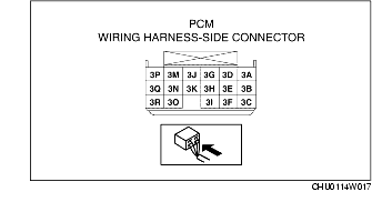
• PCM terminal 3A (FP2)
-
• PCM terminal 3D (RP2)
-
– If the signal wave pattern can be verified, inspect the following and repair or replace the malfunctioning part.
-
• Mass air flow sensor
-
• Throttle position sensor
-
• Intake air temperature sensor
5. Verify that there is output of the fuel injector (FP2, RP2) control signal wave pattern from the following PCM terminals when the PID RPM is 6,250 rpm or more.
-
• PCM terminal 3A (FP2)
-
• PCM terminal 3D (RP2)
-
– If the signal wave pattern cannot be verified, perform the following inspections and repair or replace the malfunctioning location.
-
Fuel injector (FP2)
-
• Open or short circuit in the wiring harness between PCM terminal 3A and fuel injector (FP2) terminal B

-
• Open circuit in the wiring harness between fuel injector (FP2) terminal A and main relay terminal C
-
• Fuel injector short circuit (FP2)
-
Fuel injector (RP2)
-
• Open or short circuit between the PCM terminal 3D-fuel injector (RP2) terminal B
-
• Open circuit in the wiring harness between fuel injector (RP2) terminal A and main relay terminal C
-
• Open circuit in the fuel injector (RP2) internal circuit
Fuel injector (FS, RS) operation inspection
1. Connect the WDS or equivalent to the DLC-2.
2. Warm up the engine and idle it.
3. Monitor the following PID.
-
• Engine speed signal (RPM)
4. Verify that there is no output of the fuel injector (FS, RS) control signal wave pattern from the following PCM terminal when idling. (See PCM INSPECTION.)
-
• PCM terminal 2G (FS)
-
• PCM terminal 2D (RS)
-
– If the signal wave pattern cannot be verified, perform the following inspections and repair or replace the malfunctioning part.
-
• Mass air flow sensor
-
• Throttle position sensor
-
• Intake air temperature sensor
5. Verify that there is output of fuel injector (FP2, RP2) control signal wave pattern from the following PCM terminals when the PID RPM is 5,000 rpm or more.
-
• PCM terminal 2G (FS)
-
• PCM terminal 2D (RS)
-
– If the signal wave pattern can be verified, perform the following inspections and repair or replace the malfunctioning part.
-
Fuel injector (FS)
-
• Open or short circuit of the wiring harness between PCM terminal 2G and fuel injector (FS) terminal B
-
• Open circuit in the wiring harness between fuel injector (FS) terminal A and main relay terminal
-
• Open circuit in the fuel injector (FS) internal circuit
-
Fuel injector (RS)
-
• Open or short circuit in the wiring harness between PCM terminal 2D and fuel injector (RS) terminal B
-
• Open circuit in the wiring harness between fuel injector (RS) terminal A and main relay
-
• Open circuit in the fuel injector (RS) internal circuit
Resistance Inspection
1. Turn the ignition switch to the LOCK position.
2. Disconnect the negative battery cable. (See BATTERY REMOVAL/INSTALLATION.)
3. Remove the extension manifold. (See INTAKE-AIR SYSTEM REMOVAL/INSTALLATION.)
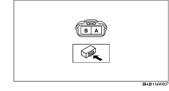
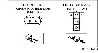
4. Disconnect the fuel injector connector.
5. Measure the resistance between terminals A and B of the fuel injector using a tester.
-
• If within the specification, perform out the "Circuit Open/Short Inspection".
-
• If not within the specification, replace the fuel injector.
-
Resistance
-
Approx. 13.8 ohms [20 °C {68 °F}]
Circuit Open/Short Inspection
1. Disconnect the PCM connector. (See PCM REMOVAL/INSTALLATION.)
2. Inspect the following wiring harness for open or short (continuity check).
Open circuit
-
• If there is no continuity, the circuit is open. Repair or replace the harness.
-
– Fuel injector (FP1) terminal B and PCM terminal 2M.
-
– Fuel injector (RP1) terminal B and PCM terminal 2J.
-
– Fuel injector (FP2) terminal B and PCM terminal 3A.
-
– Fuel injector (RP2) terminal B and PCM terminal 3D.
-
– Fuel injector (FS) terminal B and PCM terminal 2G.
-
– Fuel injector (RS) terminal B and PCM terminal 2D.
-
– Fuel injector (FP1) terminal A and main relay terminal C through common connector.
-
– Fuel injector (RP1) terminal A and main relay terminal C through common connector.
-
– Fuel injector (FP2) terminal A and main relay terminal C through common connector.
-
– Fuel injector (RP2) terminal A and main relay terminal C through common connector.
-
– Fuel injector (FS) terminal A and main relay terminal C through common connector.
-
– Fuel injector (RS) terminal A and main relay terminal C through common connector.
Short circuit
-
• If there is continuity, the circuit is short. Repair or replace the harness.
-
– Fuel injector (FP1) terminal B and body GND.
-
– Fuel injector (RP1) terminal B and body GND.
-
– Fuel injector (FP2) terminal B and body GND.
-
– Fuel injector (RP2) terminal B and body GND.
-
– Fuel injector (FS) terminal B and body GND.
-
– Fuel injector (RS) terminal B and body GND.
Leakage Inspection
-
Warning
-
• Fuel line spills and leakage from the pressurized fuel system are dangerous. Fuel can ignite and cause serious injury or death and damage. To prevent this, complete the following inspection with the engine stopped.
1. Follow the before repair procedure and perform the fuel line safety procedure. (See BEFORE REPAIR PROCEDURE.)
2. Disconnect the negative battery cable. (See BATTERY REMOVAL/INSTALLATION.)
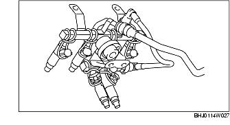
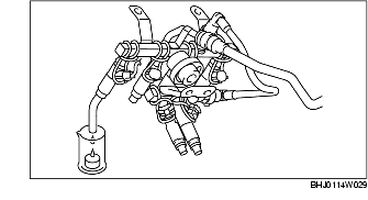
3. Remove the fuel injector and fuel distributor as a single unit. (See FUEL INJECTOR REMOVAL/INSTALLATION.)
4. Fix the fuel injector to the fuel distributor with a wire or the equivalent.
5. Connect the fuel hose.
6. Connect the negative battery cable.
-
Caution
-
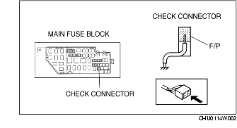
• Shorting the wrong terminal of the check connector may cause malfunctions. Make sure to short only the specified terminal.
7. Ground the check connector terminal F/P using the jumper wire.
8. Turn the ignition switch to the ON position and operate the fuel pump.
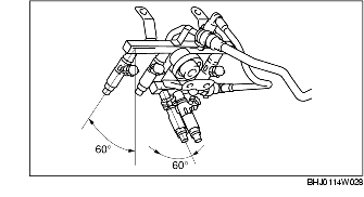
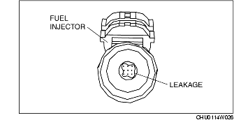
9. Tilt the fuel injector at an angle of 60° to inspect for leakage.
-
• If not within the specification, replace the fuel injector.
Test condition
-
• Fuel pressure: 392 kPa {4.00 kgf/cm2, 56.9 psi}
-
• Atmosphere temperature: Normal temperature
Leakage amount
|
Engine
|
Fuel injector
|
Leakage amount (approx.)
(1 drop)
|
|
Position
|
Color
|
|
13B-MSP
(Standard Power)
|
FP1, RP1
|
Red
|
110 min. or more
|
|
FS, RS
|
Blue
|
30 min. or more
|
|
13B-MSP
(High Power)
|
FP1, RP1
|
Red
|
110 min. or more
|
|
FP2, RP2,
FS, RS
|
Yellow
|
70 min. or more
|
10. Turn the ignition switch to the LOCK position and disconnect the jumper wire.
11. Inspect all parts by performing the "AFTER REPAIR PROCEDURE". (See AFTER REPAIR PROCEDURE.)
Injection volume Inspection
-
Warning
-
• Fuel line spills and leakage from the pressurized fuel system are dangerous. Fuel can ignite and cause serious injury or death and damage. To prevent this, complete the following inspection with the engine stopped.
1. Follow the before repair procedure and perform the fuel line safety procedure. (See BEFORE REPAIR PROCEDURE.)
2. Disconnect the negative battery cable. (See BATTERY REMOVAL/INSTALLATION.)
3. Remove the PCM. (See PCM REMOVAL/INSTALLATION.)
4. Connect the PCM connector.
5. Remove the fuel injector and fuel distributor as a single unit. (See FUEL INJECTOR REMOVAL/INSTALLATION.)
6. Fix the fuel injector to the fuel distributor with a wire or the equivalent.
7. Connect the appropriate fuel injector connector.
8. Connect the negative battery cable.
-
Caution
-
• Shorting the wrong terminal of the check connector may cause malfunctions. Make sure to short only the specified terminal.
9. Ground the check connector terminal F/P using the jumper wire.
10. Turn the ignition switch to the ON position and operate the fuel pump.
-
Caution
-
• Shorting the wrong terminal of the PCM may cause malfunctions. Make sure to short only the specified terminal.
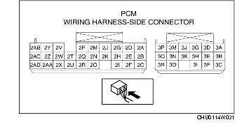
11. Ground the following PCM terminal using the jumper wire, and then measure the injection volume of each fuel injector.
-
• If not within the specification, replace the fuel injector.
Injection volume
|
Engine
|
Fuel injector
|
Injection volume (approx.)
(cm3{cc, fl oz}/15s)
|
|
Position
|
Color
|
|
13B-MSP
(Standard Power)
|
FP1, RP1
|
Red
|
69-78 {69-78, 2.4-2.6}
|
|
FS, RS
|
Blue
|
118-133 {118-133, 4.00-4.50}
|
|
13B-MSP
(High Power)
|
FP1, RP1
|
Red
|
69-78 {69-78, 2.4-2.6}
|
|
FP2, RP2,
FS, RS
|
Yellow
|
89-101 {89-101, 3.01-3.42}
|
|
Fuel injector
|
PCM terminal
|
|
Fuel injector (FP1)
|
2M
|
|
Fuel injector (RP1)
|
2J
|
|
Fuel injector (FS)
|
2G
|
|
Fuel injector (RS)
|
2D
|
|
Fuel injector (FP2)
|
3A
|
|
Fuel injector (RP2)
|
3D
|
12. Turn the ignition switch to the LOCK position and disconnect the jumper wire.
13. Inspect all parts by performing the "AFTER REPAIR PROCEDURE". (See AFTER REPAIR PROCEDURE.)
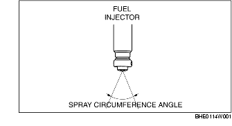
Atomization Inspection
1. Inspect the atomization status.
-
• If the spray circumference angle is incorrect or the spray density is uneven, replace the fuel injector.
Spray circumference angle
|
Engine
|
Fuel injector
|
Spray circumference angle (approx.)
|
|
Position
|
Color
|
|
13B-MSP
(Standard Power)
|
FP1, RP1
|
Red
|
26-34°
|
|
FS, RS
|
Blue
|
13-25°
|
|
13B-MSP
(High Power)
|
FP1, RP1
|
Red
|
26-34°
|
|
FP2, RP2,
FS, RS
|
Yellow
|
13-25°
|