FUEL PUMP UNIT REMOVAL/INSTALLATION
BHE011413350W01
-
Warning
-
• Fuel is extremely flammable. Always keep sparks and flame away from fuel. Ignition may cause death or serious injury, or damage to equipment.
-
• Fuel line spills and leakage from the pressurized fuel system are dangerous. Fuel can ignite and cause serious injury or death and damage. Fuel can also irritate skin and eyes. To prevent this, always complete the "Fuel Line Safety Procedure".
-
• Also, before performing the fuel pump unit removal/installation, always complete the "Fuel Leak Inspection After Fuel Pump Unit Installation".
1. Perform the fuel line safety procedure referring to the before repair procedure. (See BEFORE REPAIR PROCEDURE.)
2. Disconnect the negative battery cable. (See BATTERY REMOVAL/INSTALLATION.)
3. Remove the rear seat. (See REAR SEAT REMOVAL/INSTALLATION.)
4. Remove the service hole cover. (See Service Hole Cover Installation Note.)
5. Drain fuel from the fuel tank.
-
Warning
-
• A person charged with static electricity could cause a fire or explosion, resulting in death or serious injury. Before draining fuel, make sure to discharge static electricity by touching a vehicle.
-
Caution
-
• When the fuel gauge indicates 3/4 or more, the fuel level is higher than the installation surface of the fuel pump and the fuel suction pipe bracket. Due to this condition, fuel may spill or leak out when performing this procedure. Before performing this procedure, always drain out fuel so that the fuel tank is half full or less (according to the fuel gauge needle).
-
(1) Disconnect the quick release connector (engine compartment side). (See QUICK RELEASE CONNECTOR REMOVAL/INSTALLATION.)
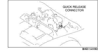
-
(2) Attach a long hose to the disconnected fuel pipe and drain the fuel into a proper receptacle.
-
(3) Ground check connector terminal F/P to the body using a jumper wire.
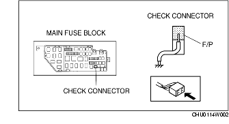
Caution
-
• Shorting the wrong terminal of the check connector may cause malfunctions. Make sure to short only the specified terminal.
-
(4) Turn the ignition switch to the ON position and operate the fuel pump for approx. 20 min.
Caution
-
• The fuel pump may malfunction if it is operated without any fuel in the fuel tank (fuel pump idling). Constantly monitor the amount of fuel being discharged and immediately stop operation of the pump when essentially no fuel is being discharged.
-
(5) When essentially no fuel is being discharged from the hose, turn the ignition switch to the LOCK position.
-
Note
-
• When operating the fuel pump with a full fuel tank, fuel discharge will become erratic after approx. 10 min but will continue for approx. 10 min more and then essentially no fuel will be discharged. At this time the fuel gauge needle will be at the halfway position.
-
(6) Disconnect the jumper wire.
-
(7) Disconnect the negative battery cable.
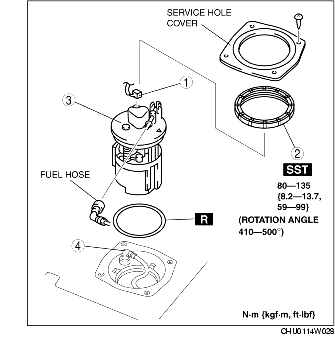
6. Remove in the order indicated in the table.
7. Install in the reverse order of removal.
|
1
|
Connector
|
|
2
|
Fuel pump cap
|
|
3
|
Fuel pump unit
|
|
4
|
Fuel suction pipe
|
Fuel Pump Cap Removal Note
-
Caution
-
• The cap could be damaged if the SST is used with any play between the cap and the SST. Securely attach the SST so that there is no gap between the SST tabs and the side of the cap.
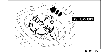
1. Remove the fuel pump cap using the SST.
Fuel Pump Unit Removal Note
-
Caution
-
• The fuel suction pipe might be damaged, if the fuel pump unit is lifted too much. Make sure to lift the pump only a small amount.
Fuel Pump Cap Installation Note
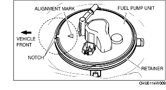
1. Align the fuel pump unit alignment marks and the retainer notch as shown in the figure.
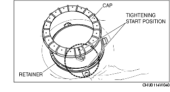
2. Align the positions of the cap and retainer as shown in the figure, and tighten them one full rotation by hand.
-
• If the retainer and cap cannot be tighten by hand, remove the cap, verify that there is no damage or misalignment on the retainer and cap, and then tighten again.
-
Caution
-
• The cap could be damaged if the SST is used with any play between the cap and the SST. Securely attach the SST so that there is no gap between the SST tabs and the side of the cap.
3. While keeping the alignment mark and the retainer notch aligned, tighten the cap to the rotation angle and specified torque using the SST.
-
• If the specified torque cannot be obtained even when the cap is rotated to the specified rotation angle, replace with a new cap and retainer and repeat Step 3.
-
Rotation angle
-
50-140°
-
(Total angle for Step 2 and Step 3 is 410-500°.)
-
Cap tightening torque
-
80-135 N· m {8.2-13.7 kgf·m, 59-99 ft·lbf}
Fuel Leak Inspection After Pump Unit Installation
1. Start driving the vehicle from a standstill or brake suddenly 5-6 times at a low speed.
2. Stop the vehicle and verify from inside the vehicle that there is no fuel leakage around the fuel pump unit.
Service Hole Cover Installation Note
1. Inspect all parts by performing the "AFTER REPAIR PROCEDURE". (See AFTER REPAIR PROCEDURE.)
2. Install the service hole cover.