SECONDARY AIR INJECTION (AIR) SOLENOID VALVE INSPECTION
BHE011613988W04
AIR System Operation Inspection
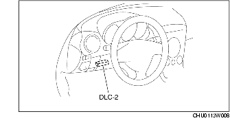
1. Connect the WDS or equivalent to the DLC-2.
2. Warm up the engine to normal operating temperature.
3. Verify that AIR pump is not operating when idling.
-
• If the AIR pump is operating, inspect the following items and repair or replace the malfunctioning location.
-
– AIR pump relay stuck closed
-
– Short circuit of the wiring harness to ground system (PCM terminal 4O-AIR pump relay terminal A)
4. When AIP RLY is turned from off to on, verify that the AIR pump relay and secondary injection pump can be heard operating.
-
• If there is no sound of operation from the AIR pump relay, inspect the following items and repair or replace the malfunction part.
-
– AIR pump relay stuck open
-
– Wiring harness, connectors: open circuit (PCM terminal 4O-AIR pump)
-
– Wiring harness, connector: open circuit (main relay terminal D-AIR pump relay terminal A)
-
• If there is no sound of operation from the AIR pump, inspect the following items and repair or replace the malfunction part.
-
– Wiring harness, connectors: open or short circuit (Battery-AIR pump relay-AIR pump terminal A)
-
– Wiring harness, connectors: open or short circuit (AIR pump terminal B-ground)
5. Inspect the discharging pressure of the AIR pump. (See Discharging Pressure Inspection.)
-
• If the discharging pressure is not as specified, replace the AIR pump.
6. Remove the vacuum hose connected to the AIR control valve.
7. Verify that vacuum hose removed when idling is not pressurized with negative pressure.
-
• If the negative pressure can be verified, perform the following inspections and repair or replace the malfunction part.
-
– AIR solenoid valve stuck open
-
– Wiring harness, connectors to ground: short circuit (PCM terminal 1O-AIR solenoid valve terminal B)
8. Verify that there is negative pressure when the AIR solenoid valve is turned on from off using the simulation function PACTNV.
-
• If the negative pressure cannot be verified, perform the following inspections and repair or replace the malfunction part.
-
– AIR solenoid valve stuck closed
-
– Wiring harness, connectors: open circuit (PCM terminal 1O-AIR solenoid valve terminal B)
-
– Vacuum hose between intake manifold, vacuum tank, AIR solenoid valve, and AIR control valve (clog, leakage, damage, poor connection)
9. Monitor the following PIDs using the monitor function.
-
• Heated oxygen sensor (front) (WDS PID: O2S11)
-
• AIR pump relay (WDS PID: AIP_RLY)
10. Warm up the engine.
11. Connect the vacuum pump to the AIR control valve.
12. Operate the AIR pump using the simulation function AIP_RLY.
-
Caution
-
• Do not operate the AIR pump for more than 1 min to avoid damaging the pump.
-
• Allow 1 h after energization for the AIR pump to cool down before operating it again.
-
• Inspect the following immediately to prevent the catalyst from becoming overheated.
13. Verify that the PID O2S11 shows a lean value when pressurizing the AIR pump using a vacuum pump while idling.
-
• If a lean value for the PID O2S11 cannot be confirmed, inspect the following items and repair or replace the applicable part.
-
– AIR control valve operation malfunction. (See SECONDARY AIR INJECTION (AIR) CONTROL VALVE INSPECTION.)
-
– Channel between AIR pump and exhaust manifold (clog, leakage)
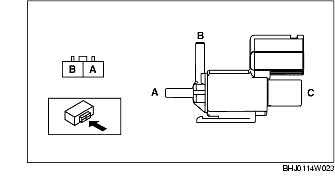
Air flow Inspection
1. Disconnect the negative battery cable. (See BATTERY REMOVAL/INSTALLATION.)
2. Remove the AIR solenoid valve. (SeeSECONDARY AIR INJECTION (AIR) SOLENOID VALVE REMOVAL/INSTALLATION.)
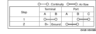
3. Inspect air flow between the ports under the following conditions:
-
• If there is no malfunction, inspect the related wiring harnesses.
-
• If there is any malfunction, replace the AIR solenoid valve. (SeeSECONDARY AIR INJECTION (AIR) SOLENOID VALVE REMOVAL/INSTALLATION.)