FRONT WHEEL ALIGNMENT
BHE021101015W01
Specification (Unloaded Condition)
Standard suspension
|
Item
|
Specification
|
|
Total toe-in
|
Tire [Tolerance ±4 mm {0.15 in}]
|
(mm {in})
|
2 {0.08}
|
|
Rim inner
|
(mm {in})
|
1.2±2.5 {0.05±0.09}
|
|
|
Degree
|
0°11'±21'
|
|
Steering angle [Tolerance ±3°]
|
Inner
|
38°41'
|
|
Outer
|
33°15'
|
|
King pin inclination (Reference value)
|
10°52'
|
|
Camber
[Tolerance ±1°]
|
Vehicle height: From the end of the front fender to the center of the wheel (mm {in})
|
367-376 {14.4-14.8}
|
-0°33'
|
|
377-386 {14.9-15.1}
|
-0°13'
|
|
387-396 {15.2-15.5}
|
0°04'
|
|
397-406 {15.6-15.9}
|
0°20'
|
|
407-416 {16.0-16.3}
|
0°33'
|
|
Caster
[Tolerance ±1°]
|
Vehicle height: From the end of the rear fender to the center of the wheel (mm {in})
|
361-370 {14.2-14.5}
|
6°31'
|
|
371-380 {14.6-14.9}
|
6°18'
|
|
381-390 {15.0-15.3}
|
6°06'
|
|
391-400 {15.4-15.7}
|
5°53'
|
|
401-410 {15.8-16.1}
|
5°40'
|
Sport suspension
|
Item
|
Specification
|
|
Total toe-in
|
Tire [Tolerance ±4 mm {0.15 in}]
|
(mm {in})
|
2 {0.08}
|
|
Rim inner
|
(mm {in})
|
1.4±2.8 {0.06±0.11}
|
|
|
Degree
|
0°11'±21'
|
|
Steering angle [Tolerance ±3°]
|
Inner
|
38°36'
|
|
Outer
|
33°07'
|
|
King pin inclination (Reference value)
|
11°02'
|
|
Camber
[Tolerance ±1°]
|
Vehicle height: From the end of the front fender to the center of the wheel (mm {in})
|
361-370 {14.2-14.5}
|
-0°45'
|
|
371-380 {14.6-14.9}
|
-0°25'
|
|
381-390 {15.0-15.3}
|
-0°06'
|
|
391-400 {15.4-15.7}
|
0°11'
|
|
401-410 {15.8-16.1}
|
0°26'
|
|
Caster
[Tolerance ±1°]
|
Vehicle height: From the end of the rear fender to the center of the wheel (mm {in})
|
354-363 {13.9-14.2}
|
6°41'
|
|
364-373 {14.3-14.6}
|
6°28'
|
|
374-383 {14.7-15.0}
|
6°16'
|
|
384-393 {15.1-15.4}
|
6°03'
|
|
394-403 {15.5-15.8}
|
5°50'
|
-
Note
-
• Unloaded vehicle: Fuel tank is full. Engine coolant and engine oil are at specified level. Jack and tools are in designated position.
-
• Difference between the left and right dimension for camber and caster is within 1°.
Steering Angle Adjustment
1. Loosen the locknut of the tie-rod end.
2. Remove the rack boot clamp.
3. Rotate the tie rod and adjust the steering angle.
-
Standard steering angle
-
Standard suspension
-
Inner: 38°41'±3°
-
Outer: 33°15'±3°
-
Sport suspension
-
Inner: 38°36'±3°
-
Outer: 33°07'±3°
-
Note
-
• Rotate and adjust the tie rod. The difference between right and left dimension L shown in the figure should be within the specification.

-
Standard
-
3 mm {0.12 in} or less
4. Tighten the locknut of the tie-rod end.
-
Tightening torque
-
37.0-49.0 N·m {3.78-4.99 kgf·m, 27.3-36.1 ft·lbf}
5. Correct the rack boot deformation.
6. Install and fix the rack boot clamp.
7. After adjusting the steering angle, always inspect and adjust the toe angle. (See Total Toe-in Adjustment.)
Camber Adjustment
-
Caution
-
• Adjust the camber before adjusting the caster.
1. Loosen the fixing nut of the adjusting cam bolt (front lower arm front side).
2. Rotate the adjusting cam bolt in either direction to adjust the camber.
Standard suspension
|
Vehicle height*
|
Camber
|
|
367-376 {14.4-14.8}
|
-0°33'±1°
|
|
377-386 {14.9-15.1}
|
-0°13'±1°
|
|
387-396 {15.2-15.5}
|
0°04'±1°
|
|
397-406 {15.6-15.9}
|
0°20'±1°
|
|
407-416 {16.0-16.3}
|
0°33'±1°
|
Sport suspension
|
Vehicle height*
|
Camber
|
|
361-370 {14.2-14.5}
|
-0°45'±1°
|
|
371-380 {14.6-14.9}
|
-0°25'±1°
|
|
381-390 {15.0-15.3}
|
-0°06'±1°
|
|
391-400 {15.4-15.7}
|
0°11'±1°
|
|
401-410 {15.8-16.1}
|
0°26'±1°
|
* :
From the end of the front fender to the center of the wheel (mm {in})
|
|
Left wheel
|
Right wheel
|
|
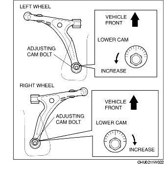
Positive direction
|
Counterclockwise
|
Clockwise
|
|
Negative direction
|
Clockwise
|
Counterclockwise
|
-
Note
-
• Refer to the following figure for the adjusting angle per one graduation of the toe-in gauge.
3. Tighten the nut.
-
Tightening torque
-
117.7-137.3 N·m {12.1-14.0 kgf·m, 86.9-101.2 ft·lbf}
4. Adjust the toe-in.
Caster Adjustment
-
Caution
-
• Adjust the caster after adjusting the camber.
1. Loosen the installation nut of the adjusting cam bolt (front lower arm rear side).
2. Rotate the adjusting cam bolt in either direction to adjust caster.
Standard suspension
|
Vehicle height*
|
Caster
|
|
361-370 {14.2-14.5}
|
6°31'
|
|
371-380 {14.6-14.9}
|
6°18'
|
|
381-390 {15.0-15.3}
|
6°06'
|
|
391-400 {15.4-15.7}
|
5°53'
|
|
401-410 {15.8-16.1}
|
5°40'
|
Sport suspension
|
Vehicle height*
|
Caster
|
|
354-363 {13.9-14.2}
|
6°41'
|
|
364-373 {14.3-14.6}
|
6°28'
|
|
374-383 {14.7-15.0}
|
6°16'
|
|
384-393 {15.1-15.4}
|
6°03'
|
|
394-403 {15.5-15.8}
|
5°50'
|
* :
From the end of the rear fender to the center of the wheel (mm {in})
|
|
Left wheel
|
Right wheel
|
|
Increase
|
Counterclockwise
|
Clockwise
|
|
Decrease
|
Clockwise
|
Counterclockwise
|
-
Note
-
• Refer to the following table for the adjusting amount per one graduation.
3. Tighten the nut.
-
Tightening torque
-
117.7-137.3 N·m {12.1-14.0 kgf·m, 86.9-101.2 ft·lbf}
4. Adjust the camber and total toe-in.
Total Toe-in Adjustment
1. Loosen the locknut of the tie-rod end.
2. Remove the rack boot clamp.
3. Adjust the total toe-in by rotating each tie rod (left and right) in the opposite directions by the same amount respectively.
-
Total Toe-in Standard
-
2±4 mm {0.08±0.15 in} (0°11'±21')
-
Note
-
• Toe angle changes by approx. 5 mm {0.2 in} per one rotation of the tie rod for one wheel.
-
• Each tie rod has a left-hand thread. When increasing the toe-in angle, rotate the right tie rod toward the rear of the vehicle, and rotate the left tie rod toward the front of the vehicle by the same amount.
4. Tighten the locknut of the tie-rod end.
-
Tightening torque
-
37.0-49.0 N·m {3.78-4.99 kgf·m, 27.3-36.1 ft·lbf}
5. Verify that the rack boot does not have any twisting, and install the rack boot clamp.