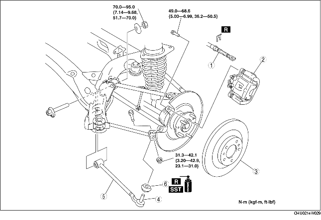
1. Remove in the order indicated in the table.
2. Install in the reverse order of removal.
3. Inspect the rear wheel alignment.
(See REAR WHEEL ALIGNMENT.)
|
1
|
Parking brake cable
|
|
2
|
Caliper component
|
|
3
|
Disc plate
|
|
4
|
Toe control link ball joint
|
|
5
|
Toe control link
|
|
6
|
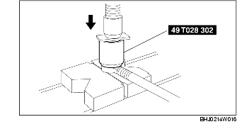
Dust boot
(See Dust Boot Installation Note.)
|
1. Hang the caliper component using the cable and move aside.
1. Wipe the grease off the ball joint stud.
2. Fill the inside of the new dust boot with grease.
3. Using the SST, install the dust boot to the ball joint.
4. Wipe off the excess grease.
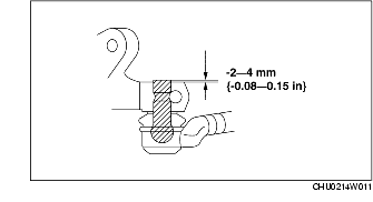
1. Install the toe control link ball joint so that the ball joint stud projection is within -2-4 mm {-0.08-0.15 in}.