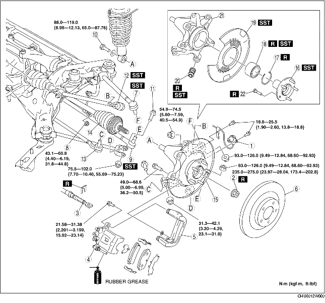
1. Remove in the order indicated in the table.
2. Install in the reverse order of removal.
3. After installation, inspect the rear wheel alignment. (See REAR WHEEL ALIGNMENT.)
|
1
|
ABS wheel-speed sensor
|
|
2
|
Locknut
(See Locknut Removal Note.)
(See Locknut Installation Note.)
|
|
3
|
Parking brake cable
|
|
4
|
Brake caliper component
|
|
5
|
Mounting support
|
|
6
|
Disc plate
(See Disc Plate Removal Note.)
(See Disc Plate Installation Note.)
|
|
7
|
Rear lateral link (upper) ball joint
|
|
8
|
Stabilizer control link (lower)
|
|
9
|
Rear lateral link (lower) ball joint
|
|
10
|
Shock absorber bolt (lower)
|
|
11
|
Rear trailing link (lower) outside bolt
|
|
12
|
Rear trailing link (upper) ball joint
|
|
13
|
Toe control link (outer)
|
|
14
|
Rear drive shaft
|
|
15
|
Rear knuckle component
|
|
16
|
Wheel hub component
|
|
17
|
Retaining ring
|
|
18
|
Wheel bearing
(See Wheel Bearing Removal Note.)
|
|
19
|
Dust cover
(See Dust Cover Removal Note.)
(See Dust Cover Installation Note.)
|
|
20
|
Bushing
(See Bushing Removal Note.)
(See Bushing Installation Note.)
|
|
21
|
Rear knuckle
|
|
22
|
Wheel hub bolt
(See Wheel Hub Bolt Removal Note.)
|
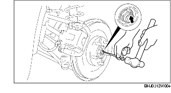
1. Lock the disc plate by applying the brakes.
2. Knock the crimped portion of the locknut outward using a chisel and a hammer.
3. Remove the locknut.
1. Suspend the brake caliper component using a cable.
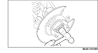
1. Temporarily install a spare nut onto the end of the rear drive shaft.
2. Tap the nut with a copper hammer to loosen the drive shaft from the wheel hub.
3. Separate the rear drive shaft from the wheel hub.
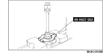
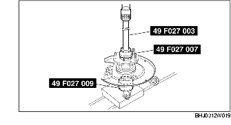
1. Remove the wheel hub component using the SSTs.
2. If the bearing inner race remains on the wheel hub component, use a chisel to secure a sufficient space for installing the SST between wheel hub component and bearing inner race.
3. Remove the bearing inner race using the SST.
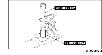
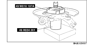
1. Remove the wheel bearing from the rear knuckle using the SSTs.
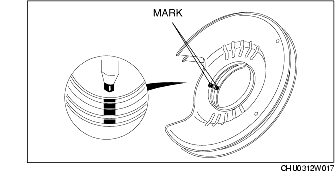
1. Place an alignment mark on the dust cover and rear knuckle for proper installation.
2. Remove the dust cover using a chisel.
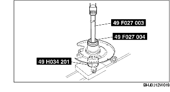
1. Remove the bushing from the rear knuckle using the SSTs.
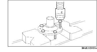
1. Remove the wheel hub bolts from the wheel hub using a press.
1. Press in new wheel hub bolts into the wheel hub using a press.
1. Press the new bushing into the rear knuckle using the SSTs.
1. Align the new and old dust covers and place alignment marks on the new dust cover.
2. Align the marks on the new dust cover and rear knuckle.
3. Press the new dust cover onto the rear knuckle using the SSTs.
1. Install a new wheel bearing using the SSTs.
1. Install the wheel hub component using the SSTs.
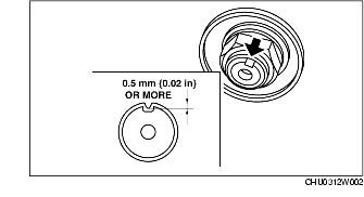
1. Tighten a new locknut.
2. Install a new locknut and indent as shown to crimp the locknut, using a chisel and hammer.