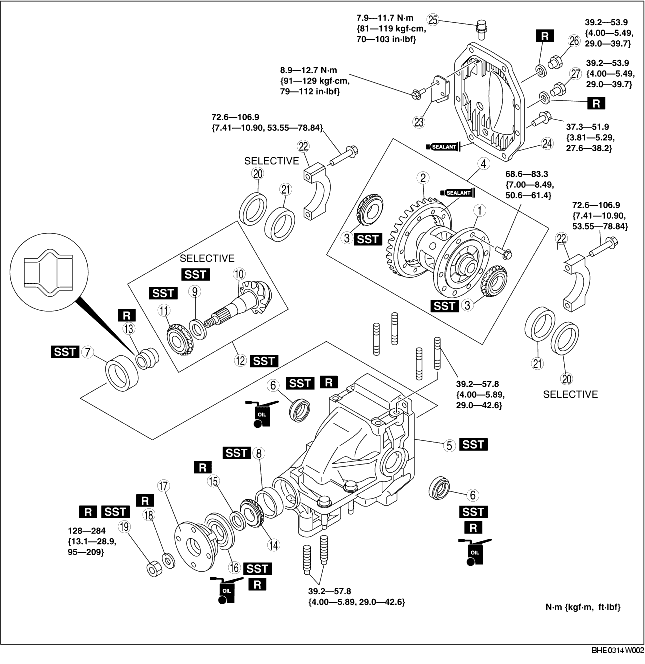
1. Assemble in the order indicated in the table.
|
1
|
Gear case
|
|
2
|
Ring gear
(See Ring Gear Assembly Note.)
|
|
3
|
Side bearing
(See Side Bearing Assembly Note.)
|
|
4
|
Differential gear case component
|
|
5
|
Differential carrier
|
|
6
|
Oil seal (side gear)
|
|
7
|
Rear bearing outer race
|
|
8
|
Front bearing outer race
|
|
9
|
Spacer
(See Spacer Assembly Note.)
|
|
10
|
Drive pinion
|
|
11
|
Rear bearing
(See Rear Bearing Assembly Note.)
|
|
12
|
Drive pinion component
|
|
13
|
Collapsible spacer
|
|
14
|
Front bearing
|
|
15
|
Spacer
|
|
16
|
Oil seal (companion flange)
|
|
17
|
Companion flange
|
|
18
|
Washer
|
|
19
|
Locknut
(See Locknut Assembly Note.)
|
|
20
|
Adjustment shim
|
|
21
|
Side bearing race
|
|
22
|
Bearing cap
(See Bearing Cap Assembly Note.)
|
|
23
|
Baffle plate
|
|
24
|
Rear cover
|
|
25
|
Bleeder plug
|
|
26
|
Oil-fill plug
|
|
27
|
Drain plug
|
1. Apply a small amount of thread-locking compound to each of points A on the back of the ring gear, and bolt thread areas B (around the entire ring).
2. Install the ring gear to the differential gear case and tighten the bolts in a criss-cross pattern.
1. Press the side bearing in using the SST and a press.
1. Apply differential oil to the lip of a new oil seal.
2. Assemble the oil seal using the SSTs.
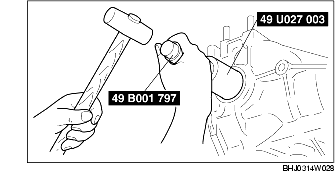
1. Press the rear bearing outer race into the differential carrier using the SST and a press.
1. Press the front bearing outer race into the differential carrier using the SST and a press.
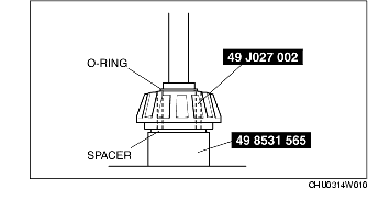
1. Assemble the spacer, bearing inner race (rear side), and the SST (O-ring) to the SST (49 8531 565) as shown in the figure.
2. Insert the set assembled in Step 1 from the rear side of the differential carrier.
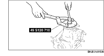
3. Assemble the SST (49 8531 567), front bearing, companion flange, and a washer from the front side of the differential carrier.
4. Tighten the locknut to the extent that the SST (49 8531 565) can be turned by hand.
5. Place the SST (49 8531 565) on top of the SST (49 0660 555).
6. Place the SST on the surface plate and set the dial gauge to zero.
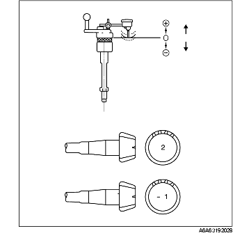
7. Set the SSTs as shown in the figure.
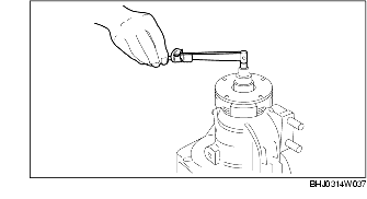
8. Place the measuring probe of the dial gauge at the point where the side bearing is installed in the differential carrier and measure at the lowest position. Measure the left and right sides.
9. Add the two (left and right) values obtained by the measurements taken in Step 8 and then divide the total by 2. From this sum, subtract the sum of the number inscribed on the end of the drive pinion divided by 100. (If there is no figure inscribed, use 0.) This is the pinion height adjustment value.
Spacer table
1. Assemble the spacer selected in the pinion height adjustment to the drive pinion.
2. Press the drive pinion into the rear bearing using the SSTs and a press.
1. Assemble the following parts to the drive pinion.
2. Turn the serrated part of the drive pinion by hand to seat the bearing.
3. Tighten the locknut temporarily tightened in Step 1 from the lower limit of the specified tightening torque using the SST, and obtain the specified preload. Record the tightening torque at this time.
4. Remove the locknut, washer, and companion flange.
1. Apply differential oil to the lip of a new oil seal.
2. Assemble the oil seal using the SST.
1. Tighten a new locknut with the torque recorded at the drive pinion preload adjustment using the SST.
2. Verify that the drive pinion preload is within the specification.
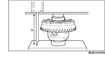
1. Stack the side bearing race and differential gear case component on the surface plate as shown in the figure, and measure the height using a caliper and a ruler. This is value A.
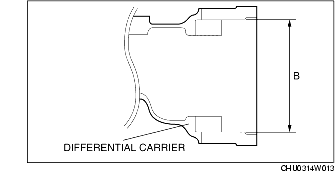
2. Measure the width of the section of the differential gear case component installed in the differential carrier. This is value B.
3. The combined thickness of the left and right adjustment shims is obtained by the following formula.
Shim thickness (mm {in}) =B-A+ (0.01-0.03 {0.0004-0.0118 in})
4. If the combined thickness of the previously assembled adjustment shims is equal to the calculated thickness, use the shims as they are.
5. If the combined thickness of the previously assembled adjustment shims is not equal to the calculated thickness, or if the adjustment shims have to be replaced, select two appropriate adjustment shims from the table below.
Adjustment shim table
6. Assemble the differential gear case component and the side bearing race to the differential carrier.
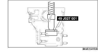
7. Tap the selected adjustment shim between the differential carrier and the side bearing race with a plastic hammer as shown in the figure.
8. Align the bearing cap alignment marks, assemble the bearing cap, and then temporarily tighten the bolts.
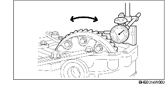
9. Install the dial gauge with the measuring probe of the dial gauge attached perpendicularly to the end of one of the ring gear teeth.
10. Secure the drive pinion and measure the backlash of the ring gear.
11. If the backlash is not within the specification, adjust the gear case component by moving it in the axial direction.
1. Align the bearing cap alignment marks and assemble the bearing cap with the arrow facing outward.
2. Perform the drive pinion and ring gear tooth contact inspection.
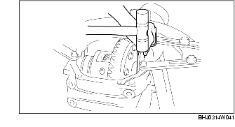
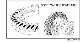
1. Apply tooth marking compound evenly to both surfaces of the ring gear.
2. Rotate the ring gear back and forth for several times.
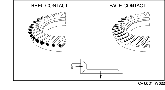
3. Inspect the tooth contact pattern in 4 locations around the ring gear, and verify that the tooth contact points exhibit the pattern as shown in the figure.
4. If the toe and flank contact points appear as shown in the figure after the drive pinion and ring gear teeth contact inspection, replace the spacer with a thinner one, and move the drive pinion outward.
5. If the heel and face contact points appear as shown in the figure after the drive pinion and ring gear teeth contact inspection, replace the spacer with a thicker one, and move the drive pinion inward.