MECHANICAL SYSTEM TEST
BHE051301026W02
Mechanical System Test Preparation
1. Engage the parking brake and use wheel chocks at the front and rear of the wheels.
2. Inspect the engine coolant level. (See ENGINE COOLANT LEVEL INSPECTION.)
3. Inspect the engine oil level. (See ENGINE OIL LEVEL INSPECTION.)
4. Inspect the ATF level. (See Automatic Transmission Fluid (ATF) Level Inspection.)
5. Inspect the idle speed and ignition timing in the P position. (See ENGINE TUNE-UP.)
6. Wait until the engine and transmission reach normal operating temperature.
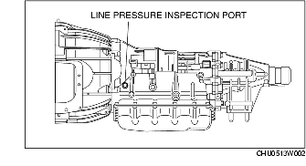
Line Pressure Test
1. Perform mechanical system test preparation. (See Mechanical System Test Preparation.)
-
Warning
-
• Removing the square head plug when the ATF is hot can be dangerous. Hot ATF can come out of the opening and badly burn you. Before removing the square head plug, allow the ATF to cool.
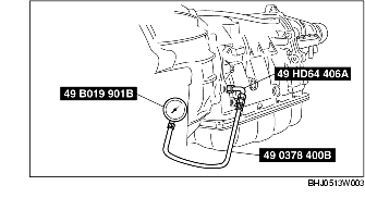
2. Connect the SSTs (49 HD64 406A, 49 0378 400B) to the line pressure inspection port and replace the gauge of the SST (49 0378 400B) with the SST (49 B019 901B).
3. Start the engine and warm it up until the ATF reaches 60-70 °C {140-158 °F}.
4. Shift the selector lever to the D range.
5. Read the line pressure while the engine is idling for the D range.
6. Read the line pressure while the engine is idling for the P, R, N positions and M range in the same manner as in Steps 4-5.
7. Stop the engine, then replace the SST (49 B019 901B) with the gauge of the SST (49 0378 400B).
8. Start the engine.
9. Firmly depress the brake pedal with the left foot.
10. Shift the selector lever to the D range.
Caution
-
• If the accelerator pedal is pressed for more than 5 s while the brake pedal is pressed, the transmission could be damaged. Therefore, perform Steps 11 and 12 within 5 s.
11. Gradually depress the accelerator pedal with the right foot.
12. When the engine speed no longer increases, quickly read the line pressure and release the accelerator pedal.
13. Shift the selector lever to the N position and idle the engine for 1 min or more to cool the ATF.
14. Read the line pressure at the engine stall speed for the M range and R position in the same manner as in Steps 9-13.
Line pressure
|
Position/Range
|
Line pressure (kPa {kgf/cm2, psi})
|
|
D, M
|
Idle
|
320-450 {3.3-4.6, 46-65}
|
|
Stall
|
1,130-1,330 {11.5-13.6, 164-193}
|
|
R
|
Idle
|
380-580 {3.9-5.9, 55-84}
|
|
Stall
|
1,470-1,700 {15.0-17.3, 213-247}
|
|
P, N
|
Idle
|
380-580 {3.9-5.9, 55-84}
|
-
Warning
-
• Removing the square head plug when the ATF is hot can be dangerous. Hot ATF can come out of the opening and badly burn you. Before removing the square head plug, allow the ATF to cool.
15. Remove the SSTs.
16. Install a new square head plug and O-ring in the inspection port.
-
Tightening torque
-
10.8-12.7 N·m {110-130 kgf·cm, 96-112 in·lbf}
Evaluation of line pressure test
|
Condition
|
Possible cause
|
|
Idle
|
Below specification
|
Low pressure in all ranges
|
Worn oil pump
Poor operation of each solenoid
Fluid leakage from oil strainer, oil pump, pressure regulator valve, torque converter relief valve, or pressure relief valve
Pressure regulator valve or pilot valve sticking
Damaged pressure regulator valve spring or pilot valve spring
|
|
Low pressure in D and M ranges only
|
Fluid leakage from hydraulic circuit of low clutch
|
|
Low pressure in R position only
|
Fluid leakage from hydraulic circuit of reverse clutch
|
|
Low pressure in M range and R position only
|
Fluid leakage from hydraulic circuit of low and reverse brake
|
|
Above specification
|
High pressure in all ranges
|
Throttle position sensor improper adjustment
TFT sensor malfunction
Poor operation of shift solenoid A
Pilot valve sticking
Pressure regulator valve or plug sticking
|
|
Stall
|
Below specification
|
Low pressure in all ranges
|
Throttle position sensor improper adjustment
Pressure control solenoid malfunction
Poor operation of shift solenoid A
Pilot valve sticking
Pressure regulator valve or plug sticking
|
Stall Speed Test
1. Perform mechanical system test preparation. (See Mechanical System Test Preparation.)
2. Start the engine.
3. Firmly depress the brake pedal with the left foot.
4. Shift the selector lever to the D range.
Caution
-
• If the accelerator pedal is pressed for more than 5 s while the brake pedal is pressed, the transmission could be damaged. Therefore, perform Steps 5 and 6 within 5 s.
5. Gently depress the accelerator pedal with the right foot.
6. When the engine speed no longer increases, quickly read the engine speed and release the accelerator pedal.
7. Shift the selector lever to the N position and idle the engine for 1 min or more to cool the ATF.
8. Perform a stall test of the M range and R position in the same manner as in Steps 3-7.
9. Turn off the engine.
Engine stall speed
|
Position/Range
|
Engine stall speed (rpm)
|
|
R, D, M
|
2,400-2,900
|
Evaluation of stall test
|
Condition
|
Possible cause
|
|
Above specification
|
In all forward ranges and R position
|
Insufficient line pressure
Worn oil pump
Poor operation of low clutch
Poor adjustment or malfunction of TR switch
Oil leakage from oil pump, control valve, or transmission case
Pressure regulator valve or pilot valve sticking
|
|
In all forward ranges
|
Low clutch slippage
Low one-way clutch slippage
|
|
In R position
|
Low and reverse brake slippage
Reverse clutch slippage
Perform road test to determine whether problem is low and reverse clutch or reverse clutch
• Engine braking felt in the M range first gear: Reverse clutch
• Engine braking not felt in M range first gear:
Low and reverse brake
|
|
Below specification
|
In all forward ranges and R position
|
Engine out of tune
One-way clutch slippage within torque converter
|
Time Lag Test
1. Perform mechanical system test preparation. (See Mechanical System Test Preparation.)
2. Start the engine.
3. Warm up the engine until the ATF temperature reaches 60-70°C {140-158°F}.
4. Shift the selector lever from the N position to D range.
5. Use a stopwatch to measure the time it takes from shifting until shock is felt. Take three measurements for each test and average from the results using the following formula.
-
Formula
-
Average time lag = (Time 1 + Time 2 + Time 3) / 3
6. Perform the test for the following shifts in the same manner Step 5.
-
• N position → R position
-
Time lag
-
N position → D range: approx. 0.2-1.3 s
-
N position → R position: approx. 0.2- 1.3 s
Evaluation of time lag test
|
Condition
|
Possible Cause
|
|
Above specification
|
N → D shift
|
Insufficient line pressure in all forward ranges
Low clutch slippage
Low one-way clutch slippage
|
|
N → R shift
|
Insufficient line pressure in R position
Low and reverse brake slippage
Reverse clutch slippage
|