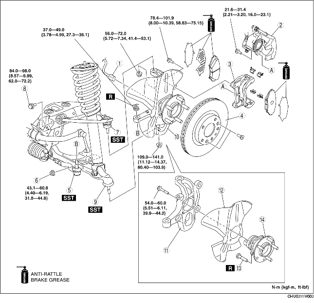
1. Remove in the order indicated in the table.
2. Install in the reverse order of removal.
3. After installation, inspect the front wheel alignment. (See FRONT WHEEL ALIGNMENT.)
|
1
|
ABS wheel-speed sensor connector
|
|
2
|
Brake caliper component
|
|
3
|
Mounting support
|
|
4
|
Disc plate
|
|
5
|
Tie-rod end
(See Tie-rod End Removal Note.)
|
|
6
|
Stabilizer control link (lower)
|
|
7
|
Front upper arm ball joint
|
|
8
|
Front upper arm bolt
|
|
9
|
Front lower arm ball joint
|
|
10
|
Wheel hub, steering knuckle component
|
|
11
|
Steering knuckle
|
|
12
|
Dust cover
|
|
13
|
Wheel hub bolt
|
|
14
|
Wheel hub component
|
1. Remove the brake caliper component installation bolt, and suspend the brake caliper component with a cable in place out of the way.