1. Remove the engine cover.
(See ENGINE COVER REMOVAL/INSTALLATION.)
2. Remove the battery cover.
3. Disconnect the negative battery cable.
4. Drain the transmission oil.
(See TRANSMISSION OIL REPLACEMENT [R15M-D].)
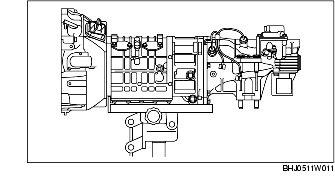
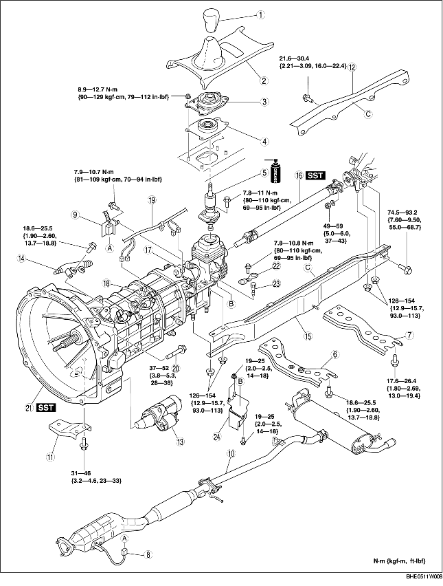
5. Remove in the order indicated in the table.
6. Install in the reverse order of removal.
7. Add the transmission oil.
(See TRANSMISSION OIL REPLACEMENT [R15M-D].)
8. Perform the 'INSPECTION AFTER TRANSMISSION INSTALLATION', and verify that there is no abnormality.
(See INSPECTION AFTER TRANSMISSION INSTALLATION [R15M-D].)
.
|
1
|
Shift lever knob
|
|
2
|
Upper panel
|
|
3
|
Shift insulator component (outer)
|
|
4
|
Shift insulator component (inner)
|
|
5
|
Shift lever component
|
|
6
|
Front tunnel member
|
|
7
|
Rear tunnel member
|
|
8
|
HO2S connector
|
|
9
|
HO2S connector bracket
|
|
10
|
Catalytic converter, middle pipe, main silencer
|
|
11
|
Exhaust manifold stay
|
|
12
|
Heat insulator
|
|
13
|
Starter
(See STARTER REMOVAL/INSTALLATION.)
|
|
14
|
Clutch release cylinder
|
|
15
|
Power plant frame
|
|
16
|
Propeller shaft
(See Propeller Shaft Removal Note.)
|
|
17
|
Back-up light switch connector
|
|
18
|
Neutral switch connector
|
|
19
|
Wire
|
|
20
|
Transmission installation bolt
|
|
21
|
Transmission
(See Transmission Removal Note.)
|
|
22
|
Stopper
|
|
23
|
Bolt
|
|
24
|
Dynamic damper
|
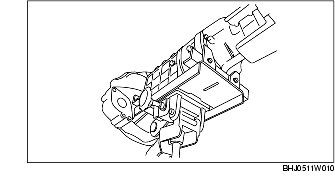
1. Support the transmission using a transmission jack.
2. Remove the power plant frame.
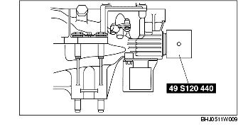
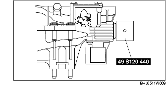
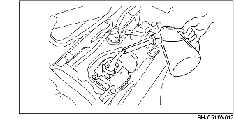
1. Install the SST to the main shaft.
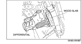
2. Insert a slab of wood behind the differential, and remove the propeller shaft.

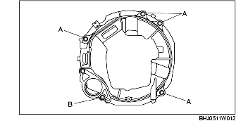
1. Support the transmission securely using a transmission jack.
2. Remove the transmission installation bolts.
3. Remove the transmission.
1. Shift to any gear position.
2. Install the SST to the main shaft.
3. Place the transmission on the transmission jack and raise it.
4. Install the transmission.
5. Tighten the transmission installation bolts.
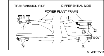
1. Using a transmission jack, support the transmission so that it is level with the differential.
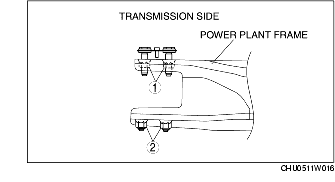
2. Install the power plant frame.
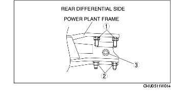
3. Temporarily tighten the nuts in the order shown in the figure.
4. Tighten nuts 1 until the power plant frame is seated in the differential.
5. Install the heat insulator, exhaust manifold stay, catalytic converter, middle pipe, main silencer, and front tunnel member.
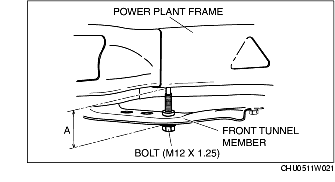
6. Raise the front end of the power plant frame (transmission side) with the transmission jack and adjust dimension A to the standard (lower end of power plant frame-lower end of the front tunnel member) as shown in the figure.
7. Tighten the nuts and bolts on the rear differential side in the order shown in the figure.
N·m {kgf·m, ft·lbf}
|
Bolt, nut number
|
Tightening torque
|
|---|---|
|
1, 2
|
126.0-154.0 {12.9-15.7, 93.0-113} |
|
3
|
74.5-93.2 {7.60-9.50, 55.0-68.7} |
8. Tighten the nuts on the rear differential side in the order shown in the figure.
9. Verify that dimension A is within the standard.
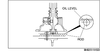
1. Add the specified type and amount of oil to the shift control case.
2. Verify that the oil is filled to near the top of the rod in the shift control case.
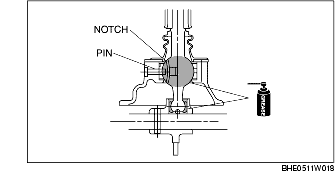
3. Apply grease to the areas of the shift lever component as shown in the figure.
4. Align the shift lever component notch with the shift control case pin and install the shift lever component.