• The OBD test inspects the integrity and function of the EPS and outputs the results when requested by the specific tests.
• On-board diagnostic test also:
• The OBD test is divided into 3 tests:
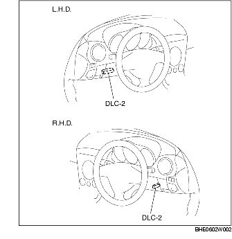
1. Connect the WDS or equivalent to the vehicle DLC-2 connector.
2. Retrieve DTCs using the WDS or equivalent.
1. After repairs have been made, perform the Reading DTCs Procedure.
2. Clear DTCs using the WDS or equivalent.
3. Verify that the customer's concern has been resolved.
1. Connect the WDS or equivalent to the vehicle DLC-2 connector.
2. Access and monitor PIDs using the WDS or equivalent.
1. Connect the WDS or equivalent to the vehicle DLC-2 connector.
2. Activate active command modes using the WDS or equivalent.
|
DTC
|
Diagnosis system component
|
Page
|
|---|---|---|
|
WDS or equivalent
|
||
|
B1318
|
Battery power supply
|
(See DTC B1318.)
|
|
B1342
|
EPS control module
|
(See DTC B1342.)
|
|
B2141
|
EPS system (neutral position setting not performed)
|
(See DTC B2141.)
|
|
B2278
|
Torque sensor
|
(See DTC B2278.)
|
|
C1099
|
EPS motor
|
(See DTC C1099.)
|
|
U0073
|
CAN bus communication error
|
|
|
U1900
|
CAN communication error
|
|
|
U2023
|
CAN communication error
|
|
PID Name
(Definition)
|
Unit/
Condition
|
Condition/Specification
|
Action
|
EPS control module terminal
|
|---|---|---|---|---|
|
B+
(System battery voltage value)
|
V
|
• IG switch ON: B+
|
Inspect battery. (See BATTERY INSPECTION.)
Inspect power supply circuit (such as IG switch, fuse).
|
2P
|
|
CCNT
(Number of continuous codes)
|
-
|
• DTCs are detected: 1-255
• No DTCs are detected: 0
|
Perform inspection using appropriate DTC.
|
-
|
|
EPS_MTR
(EPS motor drive signal)
|
A
|
• Steering wheel is not turned: Near 0 A
• Steering wheel is turned right: 0-127 A
• Steering wheel is turned left: 0- -128 A
|
Inspect EPS control module. (See EPS CONTROL MODULE INSPECTION.)
Inspect EPS motor circuit.
Inspect power supply circuit (such as IG switch, fuse).
|
4A, 4B
|
|
EPSLAMP
(EPS warning light output state)
|
ON/OFF
|
• EPS warning light is illuminated: ON
• EPS warning light is not illuminated: OFF
|
Inspect EPS control module. (See EPS CONTROL MODULE INSPECTION.)
Inspect instrument cluster.
|
-
|
|
RPM
(Engine speed signal)
|
RPM
|
• Engine speed 1,000 rpm: 1000RPM
|
Inspect PCM. (See PCM INSPECTION.)
|
-
|
|
TRQ_S_CORR
(System neutral position setting)
|
NM
|
• Steering wheel is not turned: Near 0 NM
(If system neutral position setting has not been performed, 31.75 NM is output.)
|
Perform EPS system neutral position setting. (See EPS SYSTEM NEUTRAL POSITION SETTING.)
|
-
|
|
TRQ_SENS
(Torque sensor signal)
|
NM
|
• Steering wheel is not turned: Near 0 NM
• Steering wheel is turned right: 0-31.75 NM
• Steering wheel is turned left: 0- -32 NM
|
Inspect torque sensor. (See TORQUE SENSOR INSPECTION.)
Inspect torque sensor circuit.
|
3A, 3B. 3C
|
|
VSS
(Vehicle speed signal)
|
KPH/MPH
|
• Vehicle is stopped:
0 KPH/0 MPH
• Vehicle speed 20 km/h {12 mph}: 20 KPH/12 MPH
|
Inspect PCM. (See PCM INSPECTION.)
Inspect instrument cluster. (See INSTRUMENT CLUSTER INSPECTION.)
Inspect DSC HU/CM. (See DSC HU/CM INSPECTION.)
|
-
|
|
Command Name
|
Definition
|
Operation
|
Note
|
|---|---|---|---|
|
TRQ_S_CAL
|
EPS system neutral position setting
|
ON/OFF
|
Ignition switch at ON
|