• The OBD test inspects the integrity and function of the DSC and outputs the results when requested by the specific tests.
• On-board diagnostic test also:
• The OBD test is divided into 3 tests:
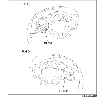
1. Connect WDS or equivalent to the vehicle DLC-2 connector.
2. Retrieve DTC using WDS or equivalent.
1. After repairs have been made, perform the DTCs reading procedure.
2. Erase DTC using WDS or equivalent.
3. Ensure that the customer's concern has been resolved.
1. Connect WDS or equivalent to the vehicle DLC-2 connector.
2. Access and monitor PIDs using WDS or equivalent.
1. Connect WDS or equivalent to the vehicle DLC-2 16-pin connector.
2. Turn the ignition switch to the ON position (engine off) or start the engine.
3. Activate active command modes using WDS or equivalent.
|
DTC
|
System malfunction location
|
Page
|
|---|---|---|
|
WDS or equivalent
|
||
|
B1318
|
Power supply system
|
(See DTC B1318.)
|
|
B1342
|
DSC HU/CM system
|
(See DTC B1342.)
|
|
B1484
|
Brake switch system
|
(See DTC B1484, C1953.)
|
|
B2477
|
DSC HU/CM configuration system
|
(See DTC B2477.)
|
|
C1093
|
DSC OFF switch system
|
(See DTC C1093.)
|
|
C1095
|
Pump motor, motor relay system
|
(See DTC C1095, C1096.)
|
|
C1096
|
Pump motor, motor relay system
|
(See DTC C1095, C1096.)
|
|
C1119
|
PCM, TCM communication system
|
(See DTC C1119, C1134.)
|
|
C1134
|
PCM, TCM communication system
|
(See DTC C1119, C1134.)
|
|
C1145
|
RF ABS wheel-speed sensor (open circuit) system
|
|
|
C1148
|
RF ABS wheel-speed sensor/ABS sensor rotor system
|
|
|
C1155
|
LF ABS wheel-speed sensor (open circuit) system
|
|
|
C1158
|
LF ABS wheel-speed sensor/ABS sensor rotor system
|
|
|
C1165
|
RR ABS wheel-speed sensor (open circuit) system
|
|
|
C1168
|
RR ABS wheel-speed sensor/ABS sensor rotor system
|
|
|
C1175
|
LR ABS wheel-speed sensor (open circuit) system
|
|
|
C1178
|
LR ABS wheel-speed sensor/ABS sensor rotor system
|
|
|
C1186
|
Valve relay system
|
(See DTC C1186, C1266.)
|
|
C1194
|
LF outlet solenoid valve system
|
|
|
C1198
|
LF inlet solenoid valve system
|
|
|
C1210
|
RF outlet solenoid valve system
|
|
|
C1214
|
RF inlet solenoid valve system
|
|
|
C1222
|
ABS wheel-speed sensor (slip monitor) system
|
(See DTC C1222.)
|
|
C1233
|
LF ABS wheel-speed sensor (short to ground) system
|
|
|
C1234
|
RF ABS wheel-speed sensor (short to ground) system
|
|
|
C1235
|
RR ABS wheel-speed sensor (short to ground) system
|
|
|
C1236
|
LR ABS wheel-speed sensor (short to ground) system
|
|
|
C1242
|
LR outlet solenoid valve system
|
|
|
C1246
|
RR outlet solenoid valve system
|
|
|
C1250
|
LR inlet solenoid valve system
|
|
|
C1254
|
RR inlet solenoid valve system
|
|
|
C1266
|
Valve relay system
|
(See DTC C1186, C1266.)
|
|
C1279
|
Combined sensor system
|
|
|
C1280
|
Combined sensor system
|
|
|
C1281
|
Combined sensor system
|
|
|
C1282
|
Combined sensor system
|
|
|
C1288
|
Brake fluid pressure sensor system
|
|
|
C1290
|
Brake fluid pressure sensor system
|
|
|
C1295
|
Steering angle sensor system
|
|
|
C1306
|
Steering angle sensor (abnormal initialization) system
|
(See DTC C1306.)
|
|
C1307
|
Steering angle sensor system
|
|
|
C1400
|
RF traction switch solenoid valve system
|
|
|
C1410
|
LF traction switch solenoid valve system
|
|
|
C1440
|
Brake fluid pressure sensor system
|
|
|
C1730
|
Brake fluid pressure sensor system
|
|
|
C1805
|
Incorrect DSC HU/CM installed
|
(SeeDTC C1805.)
|
|
C1937
|
Steering angle sensor system
|
|
|
C1938
|
Steering angle sensor system
|
|
|
C1951
|
Combined sensor system
|
|
|
C1952
|
Combined sensor system
|
|
|
C1953
|
Brake switch system
|
(See DTC B1484, C1953.)
|
|
C1954
|
Brake fluid pressure sensor system
|
|
|
C1956
|
Steering angle sensor system
|
|
|
C1957
|
RF DSC switch solenoid valve system
|
|
|
C1958
|
LF DSC switch solenoid valve system
|
|
|
C1959
|
Combined sensor system
|
|
|
C1994
|
DSC control system
|
(See DTC C1994.)
|
|
C2768
|
Combined sensor system
|
|
|
C2778
|
Steering angle sensor (abnormal battery voltage) system
|
(See DTC C2778.)
|
|
U1900
|
CAN communication system
|
|
|
U2516
|
CAN communication system
|
|
PID name (definition)
|
Unit/Condition
|
Operation condition (reference)
|
Action
|
DSC HU/CM terminal
|
|---|---|---|---|---|
|
ABS_LAMP
(ABS warning light driver output state)
|
On/Off
|
• ABS warning light illuminated: On
• ABS warning light not illuminated: Off
|
Inspect the ABS warning light.
|
-
|
|
ABS_VOLT
(System battery voltage value)
|
V
|
• Ignition switch at ON: Approx. 12.2 V
• Idling: Approx. 14.1 V
|
Inspect power supply circuit.
(See DSC SYSTEM INSPECTION.)
|
K
|
|
ABSLF_I
(Left front ABS pressure retention solenoid valve output state)
|
On/Off
|
• Solenoid valve activated: On
• Solenoid valve not activated: Off
|
Inspect the DSC HU/CM.
(See DSC HU/CM INSPECTION.)
|
-
|
|
ABSLF_O
(Left front ABS pressure reduction solenoid valve output state)
|
On/Off
|
• Solenoid valve activated: On
• Solenoid valve not activated: Off
|
Inspect the DSC HU/CM.
(See DSC HU/CM INSPECTION.)
|
-
|
|
ABSLR_I
(Left rear ABS pressure retention solenoid valve output state)
|
On/Off
|
• Solenoid valve activated: On
• Solenoid valve not activated: Off
|
Inspect the DSC HU/CM.
(See DSC HU/CM INSPECTION.)
|
-
|
|
ABSLR_O
(Left rear ABS pressure reduction solenoid valve output state)
|
On/Off
|
• Solenoid valve activated: On
• Solenoid valve not activated: Off
|
Inspect the DSC HU/CM.
(See DSC HU/CM INSPECTION.)
|
-
|
|
ABSRF_I
(Right front ABS pressure retention solenoid valve output state)
|
On/Off
|
• Solenoid valve activated: On
• Solenoid valve not activated: Off
|
Inspect the DSC HU/CM.
(See DSC HU/CM INSPECTION.)
|
-
|
|
ABSRF_O
(Right front ABS pressure reduction solenoid valve output state)
|
On/Off
|
• Solenoid valve activated: On
• Solenoid valve not activated: Off
|
Inspect the DSC HU/CM.
(See DSC HU/CM INSPECTION.)
|
-
|
|
ABSRR_I
(Right rear ABS pressure retention solenoid valve output state)
|
On/Off
|
• Solenoid valve activated: On
• Solenoid valve not activated: Off
|
Inspect the DSC HU/CM.
(See DSC HU/CM INSPECTION.)
|
-
|
|
ABSRR_O
(Right rear ABS pressure reduction solenoid valve output state)
|
On/Off
|
• Solenoid valve activated: On
• Solenoid valve not activated: Off
|
Inspect the DSC HU/CM.
(See DSC HU/CM INSPECTION.)
|
-
|
|
BOO_ABS
(Brake pedal switch input)
|
On/Off
|
• Brake pedal depressed: On
• Brake pedal released: Off
|
Inspect the brake switch.
|
AD
|
|
BRAKE_LMP
(BRAKE system warning light output state)
|
On/Off
|
• Brake system warning light illuminated: On
• Brake system warning light not illuminated: Off
|
Inspect the brake system warning light.
|
-
|
|
CCNTABS
(Number of continuous codes)
|
-
|
• DTCs detected: 1-255
• No DTCs detected: 0
|
Perform the DTC inspection.
|
-
|
|
L_DSC O
|
On/Off
|
• Solenoid valve activated: On
• Solenoid valve not activated: Off
|
Inspect the DSC HU/CM.
(See DSC HU/CM INSPECTION.)
|
-
|
|
LAT ACC
|
G
|
• Vehicle stopped or driving at constant speed: 0 G
• Cornering to right: Changes 0 G-positive
• Cornering to left: Changes 0 G-negative
|
Inspect the combined sensor.
|
G
|
|
LF_WSPD
(Left front ABS wheel-speed sensor input)
|
KPH, MPH
|
• Vehicle stopped: 0 KPH, 0 MPH
• Vehicle running: vehicle speed
|
Inspect the ABS wheel-speed sensor.
|
AJ, AL
|
|
LR_WSPD
(Left rear ABS wheel-speed sensor input)
|
KPH, MPH
|
• Vehicle stopped: 0 KPH, 0 MPH
• Vehicle running: Vehicle speed
|
Inspect the ABS wheel-speed sensor.
|
AH, AK
|
|
MCYLIP
|
kPa, psi, Bar
|
• Brake pedal released: 0 kPa, 0 psi, 0 Bar
• Brake pedal depressed: Changes according to the brake fluid pressure
|
Inspect the brake fluid pressure sensor.
|
-
|
|
PMPSTAT
(Pump motor output state)
|
On/Off
|
• Pump motor activated: On
• Pump motor not activated: Off
|
Inspect the DSC HU/CM.
(See DSC HU/CM INSPECTION.)
|
-
|
|
R_DSC O
|
On/Off
|
• Solenoid valve activated: On
• Solenoid valve not activated: Off
|
Inspect the DSC HU/CM.
(See DSC HU/CM INSPECTION.)
|
-
|
|
RF_WSPD
(Right front ABS wheel-speed sensor input)
|
KPH, MPH
|
• Vehicle stopped: 0 KPH, 0 MPH
• Vehicle running: vehicle speed
|
Inspect the ABS wheel-speed sensor.
|
AC, AE
|
|
RPM
(Engine speed signal input)
|
RPM
|
• Engine stopped: 0 RPM
• Engine speed at 3,000 rpm: 3,000 RPM
|
Inspect the PCM.
Inspect the instrument cluster.
|
-
|
|
RR_WSPD
(Right rear ABS wheel-speed sensor input)
|
KPH, MPH
|
• Vehicle stopped: 0 KPH, 0 MPH
• Vehicle running: Vehicle speed
|
Inspect the ABS wheel-speed sensor.
|
AF, AI
|
|
SWA POS
|
°
|
• Steering wheel in neutral position (not turned): 0°
• Steering wheel turned to left: Changes 0°-negative
• Steering wheel turned to right: Changes 0°-positive
|
Inspect the steering angle sensor.
|
-
|
|
TC LVAL
|
On/Off
|
• Solenoid valve activated: On
• Solenoid valve not activated: Off
|
Inspect the DSC HU/CM.
(See DSC HU/CM INSPECTION.)
|
-
|
|
TC RVAL
|
On/Off
|
• Solenoid valve activated: On
• Solenoid valve not activated: Off
|
Inspect the DSC HU/CM.
(See DSC HU/CM INSPECTION.)
|
-
|
|
TPI
|
%
|
• Closed throttle position: 0%
• Wide open throttle: Changes according to throttle valve opening angle
|
Inspect the throttle position sensor.
|
-
|
|
YAW_RATE
|
deg./s
|
• Vehicle stopped or driving straight: 0 deg./s
• Cornering to left: Changes 0 deg./s-negative
• Cornering to right: Changes 0 deg./s-positive
|
Inspect the combined sensor.
|
F
|