1. Remove the engine cover.
2. Remove the battery cover.
3. Disconnect the negative battery cable.
4. Remove the following parts.
5. Shift the selector lever to the P position.
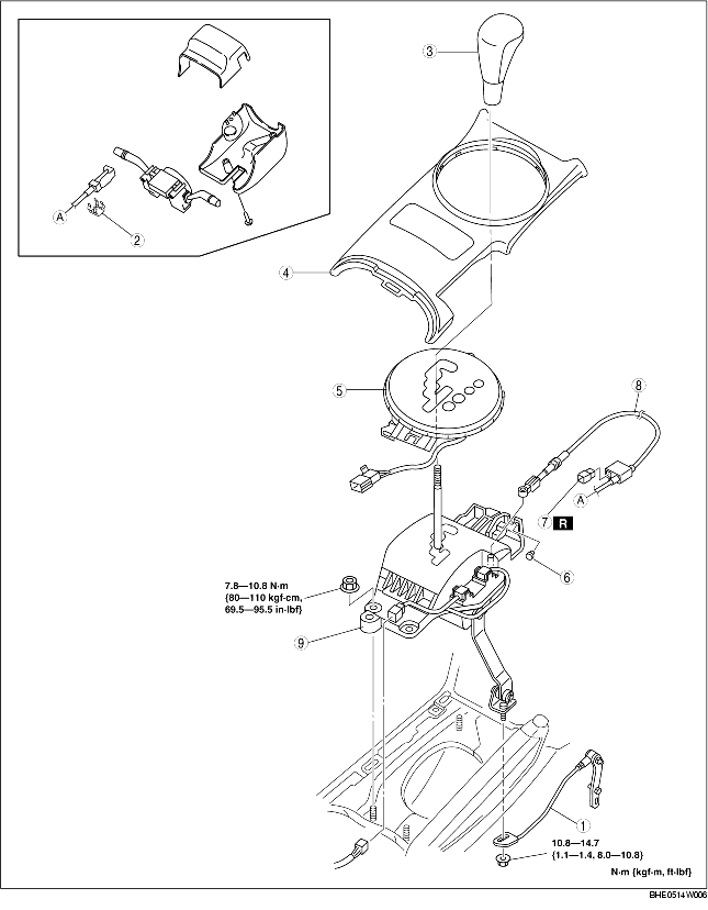
6. Remove in the order indicated in the table.
7. Install in the reverse order of removal.
8. After installation, carry out the shift lock inspection and key interlock inspection.
(See SHIFT LOCK INSPECTION.)
(See KEY INTERLOCK INSPECTION.)
|
1
|
Manual shaft lever component
|
|
2
|
Clip
|
|
3
|
Shift knob
|
|
4
|
Console panel
|
|
5
|
Indicator component
|
|
6
|
Clip
|
|
7
|
Brake switch
|
|
8
|
Interlock cable
|
|
9
|
Selector lever
|
1. Mark the manual shaft lever component as shown in the figure.
2. Remove the manual shaft lever component installation nut.
1. Verify that the selector lever is in the P position.
2. With the slider pin pressed in, slide the lock unit to fix the lock unit hook into the bracket hole securely as shown in the figure.
3. Verify that the slider pin slides freely, and rotate the slider pin to release the lock.
4. Remove your hand from the slider pin and verify that the end of the slider pin interferes with the stopper rubber of the brake pedal.
5. From this position, push the slider pin and rotate to lock.
6. Connect the brake switch connector when the brake pedal has completely returned.
7. Install the interlock cable end onto the interlock link on the selector lever.
8. Fit the interlock cable in the U-groove in the selector lever base plate and install the clip.
9. Press the interlock cable lock piece in until it is locked.
10. Remove the snap pin as shown in the figure.
11. Turn the ignition switch to the ACC position.
12. Install the interlock cable to the key cylinder.
13. Slide the outer casing to the key cylinder and insert the clip over the convex part of the outer casing.
14. After installation, carry out the shift lock inspection, interlock inspection and brake switch inspection.
(See SHIFT LOCK INSPECTION.)
(See KEY INTERLOCK INSPECTION.)
(See BRAKE SWITCH INSPECTION.)
1. Align the mark of the manual shaft lever component as shown in the figure.
2. Install the manual shaft lever component installation nut.


