1. Remove the engine cover. (See ENGINE COVER REMOVAL/INSTALLATION.)
2. Remove the battery cover.
3. Disconnect the negative battery cable.
4. Drain the ATF. (See AUTOMATIC TRANSMISSION FLUID (ATF) REPLACEMENT.)
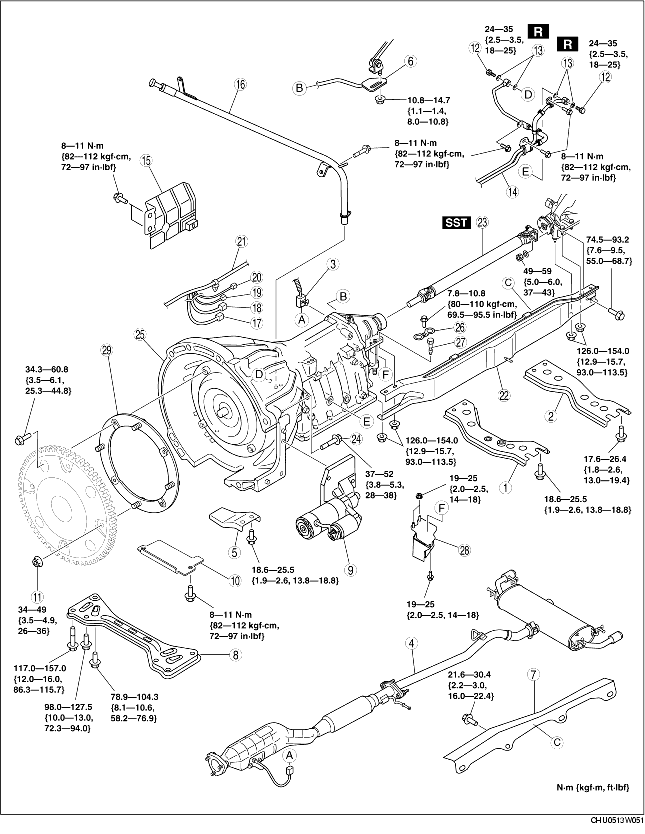
5. Remove in the order indicated in the table.
6. Install in the reverse order of removal.
7. Add ATF and, with the engine idling, inspect the ATF level and inspect for leakage. (See AUTOMATIC TRANSMISSION FLUID (ATF) REPLACEMENT.) (See Automatic Transmission Fluid (ATF) Level Inspection.)
8. Inspect selector lever operation. (See SELECTOR LEVER INSPECTION.)
9. Inspect for leakage of ATF from all connecting points.
10. Perform the mechanical system test. (See MECHANICAL SYSTEM TEST.)
11. Perform the road test. (See ROAD TEST.)
|
1
|
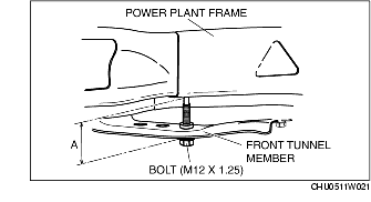
Front tunnel member
|
|
2
|
Rear tunnel member
|
|
3
|
Heated oxygen sensor connector
|
|
4
|
Catalytic converter, middle pipe, main silencer
|
|
5
|
Exhaust manifold stay
|
|
6
|
Manual shaft lever component
|
|
7
|
Heat insulator
|
|
8
|
Transverse member
|
|
9
|
Starter
(See STARTER REMOVAL/INSTALLATION.)
|
|
10
|
Under cover
|
|
11
|
Torque converter installation nuts
|
|
12
|
Connector bolt
|
|
13
|
Washer
|
|
14
|
Oil pipe, oil hose
|
|
15
|
Insulator
|
|
16
|
Oil filter tube, Dipstick
|
|
17
|
TR switch connector
|
|
18
|
Solenoid valve connector
|
|
19
|
VSS connector
|
|
20
|
Turbine sensor connector
|
|
21
|
Wire
|
|
22
|
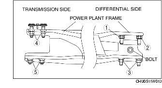
Power plant frame
|
|
23
|
Propeller shaft
(See Propeller Shaft Removal Note.)
|
|
24
|
Transmission installation bolt
|
|
25
|
Transmission
(See Transmission Removal Note.)
|
|
26
|
Stopper
|
|
27
|
Bolt
|
|
28
|
Dynamic dumper
|
|
29
|
Driven plate
|
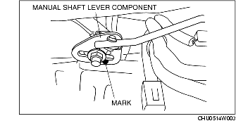
1. Mark the manual shaft lever component as shown in the figure.
2. Remove the manual shaft lever component installation nut.
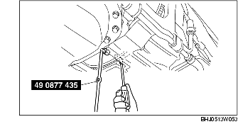
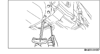
1. Lock the drive plate using a flathead screwdriver as shown in the figure.
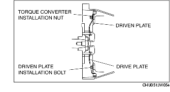
2. Remove the torque converter installation nuts using a SST.
3. Loosen the driven plate installation bolts.
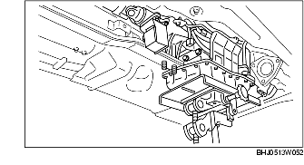
1. Support the transmission using a transmission jack.
2. Remove the power plant frame.
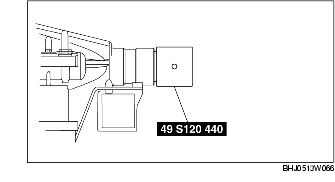
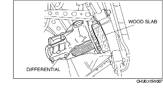
1. Install the SST to the output shaft.
2. Insert a slab of wood behind the differential and remove the propeller shaft.
1. Support the transmission securely using a transmission jack.
2. Remove the transmission installation bolt.
1. Support the transmission securely using a transmission jack.
2. Install the driven plate to the transmission (torque converter), and temporarily tighten.
3. Tighten the transmission mounting bolts.
1. Support the transmission and differential so that they are level using a transmission jack.
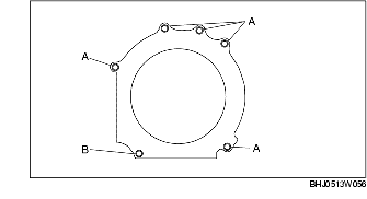
2. Install the power plant frame.
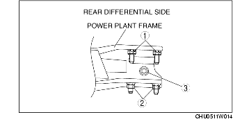
3. Temporarily tighten the nuts in the order shown in the figure.
4. Tighten nut 1 until the power plant frame is seated in the differential.
5. Install the heat insulator, exhaust manifold stay, catalytic converter\main silencer and front tunnel member.
6. Raise the front end of the power plant frame (transmission side) with the transmission jack and adjust dimension A to the standard (lower end of power plant frame-lower end of the front tunnel member) as shown in the figure.
7. Tighten the nuts and bolts on the differential side in the order shown in the figure.
|
Bolt, nut number
|
Tightening torque (N·m {kgf·m, ft·lbf})
|
|
1, 2
|
126.0-154.0 {12.9-15.7, 93.0-113.5} |
|
3
|
74.5-93.2 {12.9-15.7, 55.0-68.7} |
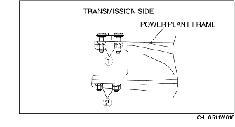
8. Tighten the nuts on the transmission side in the order shown in the figure.
9. Verify again that dimension A is within the specification.
1. Align the holes by turning the torque converter.
2. Lock the drive plate using a flathead screwdriver.
3. Tighten the torque converter installation nuts.
1. Align the mark of the manual shaft lever component as shown in the figure.
2. Install the manual shaft lever component installation nut.