1. Remove the exhaust pipe. (See EXHAUST SYSTEM REMOVAL/INSTALLATION.)
2. Remove the propeller shaft. (See PROPELLER SHAFT REMOVAL/INSTALLATION.)
3. Remove the power plant frame. (See Power Plant Frame Removal Note.) (See Power Plant Frame Removal Note.) (See Power Plant Frame Removal Note.) (See Power Plant Frame Installation Note.) (See Power Plant Frame Removal Note.) (See Power Plant Frame Installation Note.)
4. Remove the rear drive shaft. (See REAR DRIVE SHAFT REMOVAL/INSTALLATION.)
5. Remove the rear differential. (See REAR DIFFERENTIAL REMOVAL/INSTALLATION.)
6. Remove in the order indicated in the table.
7. Install in the reverse order of removal.
8. Inspect the rear wheel alignment. (See REAR WHEEL ALIGNMENT.)
|
1
|
Rear stabilizer
|
|
2
|
Rear axle component
|
|
3
|
Stopper plate
|
|
4
|
Parking brake cable
|
|
5
|
Rear crossmember component
|
|
6
|
Rear trailing link (upper)
|
|
7
|
Rear trailing link (lower)
|
|
8
|
Rear lateral link (upper)
|
|
9
|
Rear lateral link (lower)
|
|
10
|
Toe control link
|
|
11
|
Rear crossmember
|
|
12
|
No.2 bushing
(See No.2 Bushing Removal Note.)
|
|
13
|
No.3 bushing
(See No.3 Bushing Removal Note.)
|
1. Support the knuckle using a jack.
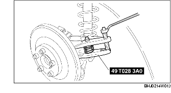
2. Using the SST, disconnect the rear trailing link (upper) ball joint.
3. Remove the rear trailing link (lower) outer bolt.
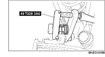
4. Using the SST, disconnect the rear lateral link (upper) ball joint.
5. Using the SST, disconnect the rear lateral link (lower) ball joint.
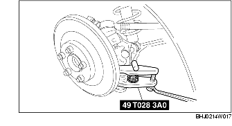
6. Remove the toe control link outer bolt.
7. Remove the shock absorber lower bolt.
8. Remove the rear axle component.
1. Support the rear crossmember with the jack, and remove the bolt.
2. Remove the rear crossmember component.
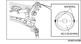
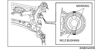
1. Mark the rear crossmember with the bushing hole aligned as shown in the figure.
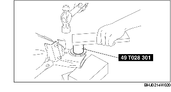
2. Using the SST, remove the bushing.
1. Mark the rear crossmember with the bushing hole aligned as shown in the figure.
2. Using the SST, remove the bushing.
1. Install the new bushing according to the marking made during bushing removal.
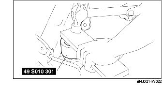
2. Using the SST, press fit the bushing.
1. Install the new bushing according to the marking made during bushing removal.
2. Using the SST, press fit the bushing.