1. Park the vehicle on a level surface.
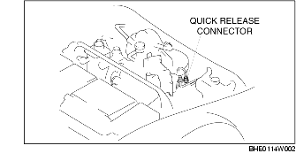
2. Perform the fuel line safety procedure referring to the before repair procedure. (See BEFORE REPAIR PROCEDURE.)
3. Remove the rear seat. (See REAR SEAT REMOVAL/INSTALLATION.)
4. Drain fuel from the fuel tank.
Caution
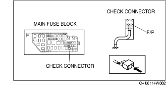
- • Shorting the wrong terminal of the check connector may cause malfunctions. Make sure to short only the specified terminal.
Caution
- • The fuel pump may malfunction if it is operated without any fuel in the fuel tank (fuel pump idling). Constantly monitor the amount of fuel being discharged and immediately stop operation of the pump when essentially no fuel is being discharged.
5. Remove the following parts:
6. Position the parking brake cable out of the way. (See PARKING BRAKE LEVER REMOVAL/INSTALLATION.)
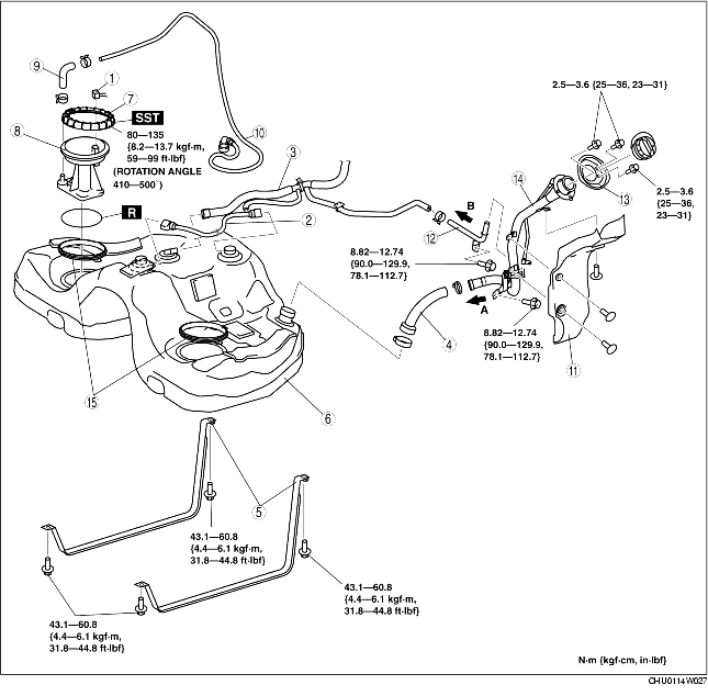
7. Remove in the order indicated in the table.
8. Install in the reverse order of removal.
9. Inspect all parts by performing the "AFTER REPAIR PROCEDURE". (See AFTER REPAIR PROCEDURE.)
|
1
|
Connector
|
|
2
|
Evaporative hose
(See Rollover Valve.)
|
|
3
|
Breather hose
(See Fuel Shut-off Valve.)
|
|
4
|
Joint hose
(See Joint Hose Installation Note.)
|
|
5
|
Strap
|
|
6
|
Fuel tank
|
|
7
|
Cap
(See Cap Removal Note.)
(See Cap Installation Note.)
|
|
8
|
Fuel suction pipe bracket
|
|
9
|
Fuel suction hose
|
|
10
|
Fuel suction pipe
|
|
11
|
Protector
|
|
12
|
Joint pipe
|
|
13
|
Dust cover
|
|
14
|
Fuel-filler pipe
|
|
15
|
Retainer
|
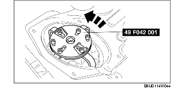
1. Remove the cap using the SST.
1. Remove the rear ABS wheel-speed sensor. (See REAR ABS WHEEL-SPEED SENSOR REMOVAL/INSTALLATION.)
2. Remove the rear shock absorber lower bolt. (See REAR SHOCK ABSORBER AND COIL SPRING REMOVAL/INSTALLATION.)
3. Loosen the rear crossmember installation nut (6 locations), and lower the rear crossmember. (See REAR CROSSMEMBER REMOVAL/INSTALLATION.)
4. Remove the fuel-filler pipe.
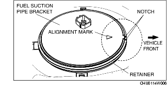
1. Align the alignment mark of the fuel suction pipe bracket and the retainer notch as shown in the figure.
2. Align the positions of the cap and retainer as shown in the figure, and tighten them one full rotation by hand.
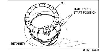
3. While keeping the alignment mark and the retainer notch aligned, tighten the cap to the rotation angle and specified torque using the SST.
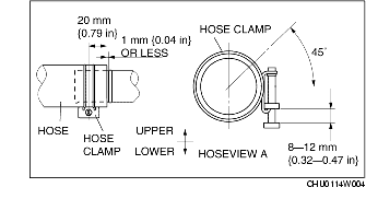
1. Install the joint hose and clamps as shown in the figure.